4.7
Date Code 20100129 Instruction Manual SEL-751A Relay
Protection and Logic Functions
Basic Protection
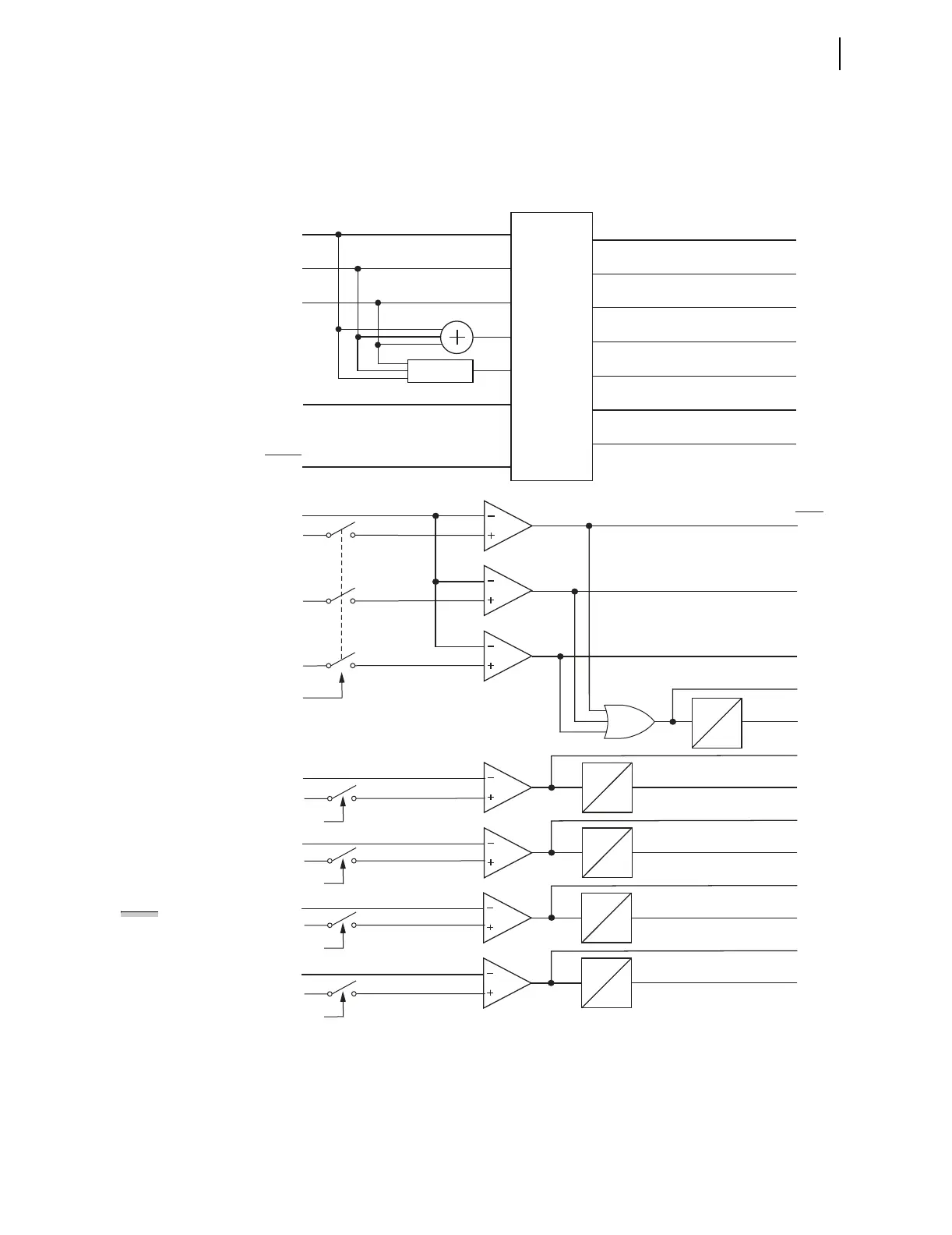
The relay offers two types of ground fault detecting overcurrent elements. The
neutral overcurrent elements (50N1T through 50N4T) operate with current
measured by the IN input. The residual (RES) overcurrent elements (50G1T
through 50G4T) operate with the current derived from the phase currents (see
Figure 4.1).
Figure 4.1 Instantaneous Overcurrent Element Logic
50P1P
|IA|
IA
IB
IC
IN
PHROT
IG
Current
Magnitude
Calculations
|IP|
|IN|
|IG|
50A1P
50B1P
|IC|
50C1P
50P1TC
50P1T
50PxP
50PxT
50NnP
50NnT
Settings
(Maximum Phase Current Magnitude)
(Core-Balance Current Magnitude)
(Residual Current Magnitude)
50NnD
0
50PxD
0
Negative-Sequence
Current Calculation
(Negative-Sequence Current Magnitude)
|3I2|
Relay
Word
Bits
50GnP
50GnT
50QnP
50QnT
50QnD
0
50GnD
0
|IA|
|IB|
(Phase A Current Magnitude)
(Phase B Current Magnitude)
(Phase C Current Magnitude)
|IC|
50P1D
0
50P1P
|IB|
50QnP
50GnP
50NnP
50PxP
|3I2|
50QnTC
|IG|
50GnTC
|IN|
50NnTC
|IP|
50PxTC
Torque Control switch position = Closed when corresponding control
bit is asserted (e.g., 50P1TC = 1), Open when it is de-asserted.
x = 2, 3, or 4
n = 1, 2, 3, or 4
NOTE: Not shown in the
figure, Relay Word Bit
ORED50T is asserted if any
of the 50PnT, 50NnT,
50GnT, or 50QnT Relay
Word Bits are asserted
(n = 1 to 4).