4.43
Date Code 20100129 Instruction Manual SEL-751A Relay
Protection and Logic Functions
Voltage-Based Protection
EPWR := 3P1 enables one three-phase power element. Set EPWR := 3P2 if
you want to use both elements.
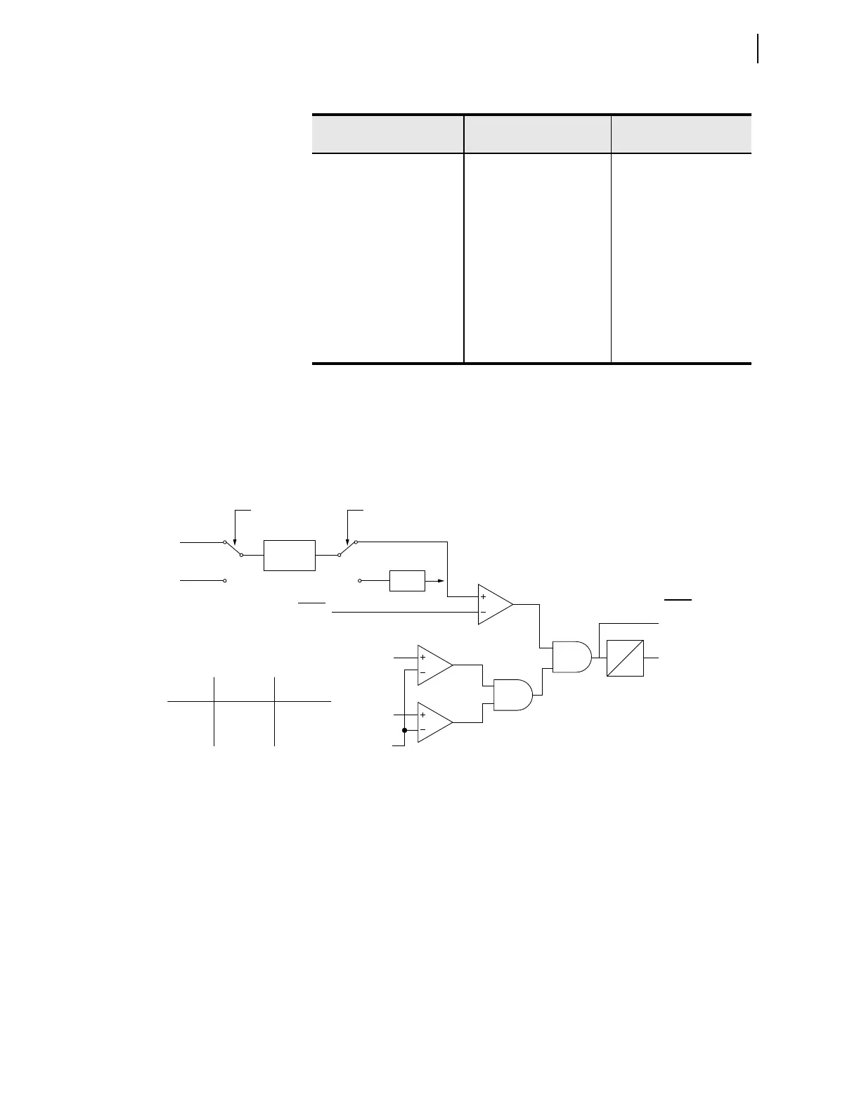
Set the element pickup, 3PH PWR ELEM PU to desired values. Figure 4.23
shows the power element logic diagram and Figure 4.24 shows the operation
in the Real/Reactive power plane.
Figure 4.23 Three-Phase Power Elements Logic
Table 4.20 Power Element Settings
Setting Prompt Setting Range
Setting Name :=
Facto ry Defau lt
ENABLE PWR ELEM N, 3P1, 3P2 EPWR := N
3PH PWR ELEM PU OFF, 1.0–6500.0 VA
a
a
The range shown is for 5 A input; range for 1 A input is OFF, 0.2—1300.0 VA.
3PWR1P := OFF
PWR ELEM TYPE +WATTS, –WATTS,
+VARS, –VARS
PWR1T := +VARS
PWR ELEM DELAY 0.0–240.0 s PWR1D := 0.0
3PH PWR ELEM PU OFF, 1.0–6500.0 VA
a
3PWR2P := OFF
PWR ELEM TYPE +WATTS, –WATTS,
+VARS, –VARS
PWR2T := +VARS
PWR ELEM DELAY 0.0–240.0 s PWR2D := 0.0
PWRnD
0
3PWRnP
|V
AB
|
20 V
3PWRnT
Relay
Word
Bits
Switch A
Position
+WATTS
–WATTS
+VARS
–VARS
Setting
PWRnT
1
1
2
2
Switch B
Position
1
2
1
2
Where n = 1 or 2
2 Cycle
Average
•(–1)
Switch A Switch B
11
22
3PWRnP
|V
BC
|
Setting
P
Q