10.11
Date Code 20100129 Instruction Manual SEL-751A Relay
Testing and Troubleshooting
Periodic Tests (Routine Maintenance)
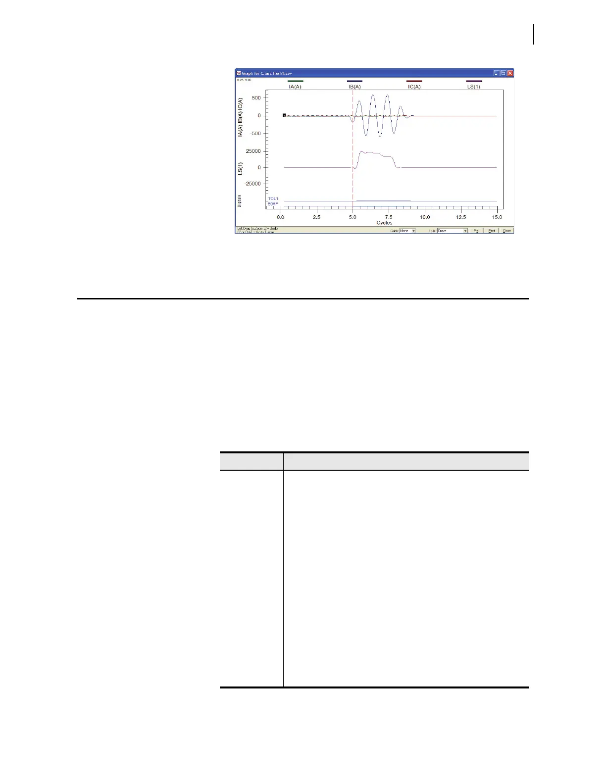
Figure 10.6 CEV R LIght Event Capture Example
Periodic Tests (Routine Maintenance)
Because the SEL-751A is equipped with extensive self-tests, the most
effective maintenance task is to monitor the front-panel messages after a self-
test failure. In addition, each relay event report generated by a fault should be
reviewed. Such reviews frequently reveal problems with equipment external to
the relay, such as instrument transformers and control wiring.
The SEL-751A does not require specific routine tests, but your operation
standards may require some degree of periodic relay verification. If you need
or want to perform periodic relay verification, the following checks are
recommended.
Table 10.6 Periodic Relay Checks
Test Description
Relay Status Use the front-panel STATUS or serial port STATUS command to ver-
ify that the relay self-tests have not detected any WARN or FAIL con-
ditions.
Arc-Flash
Detection
(AFD) Status
Use the serial port AFT command to verify that the AFD channel self-
tests have not detected any FAIL condition in any of the channels.
Meter Verify that the relay is correctly measuring current and voltage (if
included) by comparing the relay meter readings to separate external
meters.
Control Input Using the front-panel
MAIN > Targets > Row 13 function,
check the control input status in the relay. As you apply rated voltage
to each input, the position in Row 13 corresponding to that input
should change from zero (0) to one (1).
Contact Output For each output contact, set the input to Logic 1. This causes the output
contact to close. For example, setting OUT101 := 1 causes the output
OUT101 contact to close.
Repeat the process for all contact outputs. Make sure that each contact
closure does what you want it to do in the annunciation, control, or trip
circuit associated with that contact closure.