4.106
SEL-751A Relay Instruction Manual Date Code 20100129
Protection and Logic Functions
Digital Input Debounce
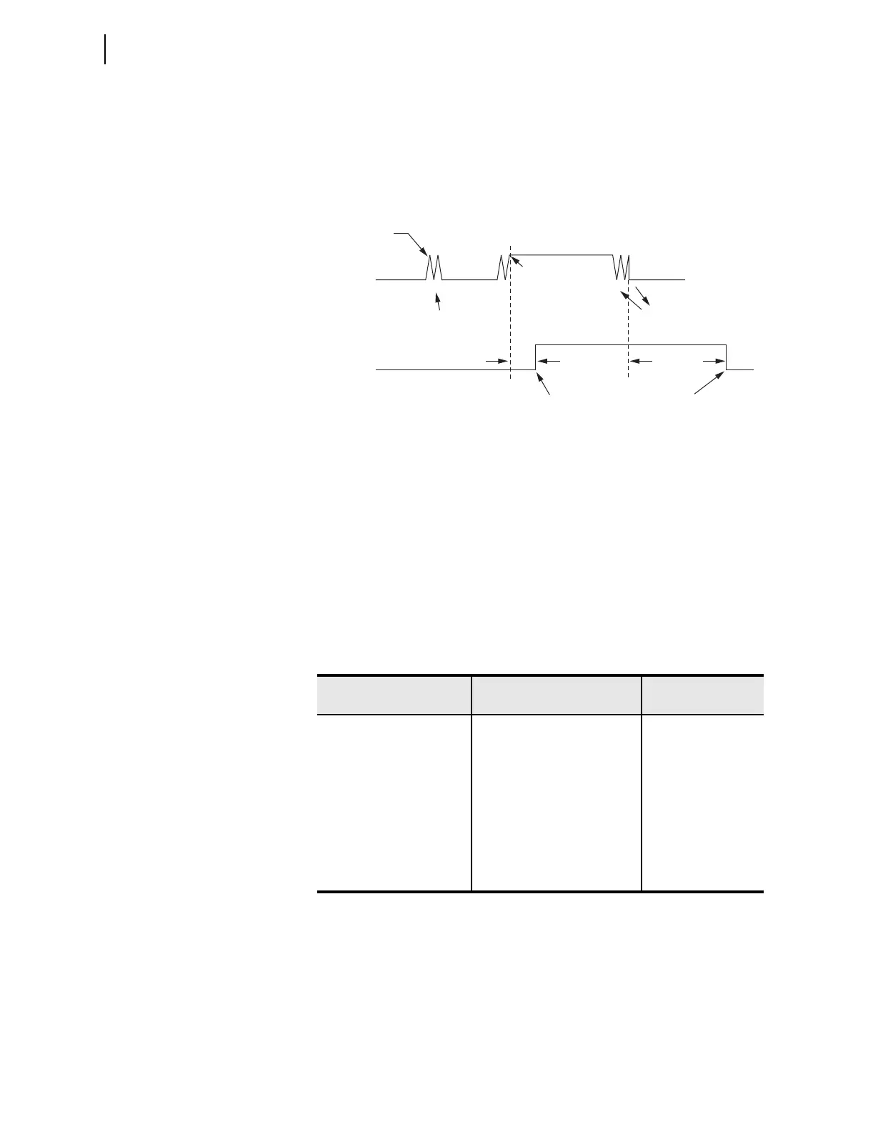
Figure 4.61 shows a timing diagram for the ac mode of operation. On the
rising edge of IN101R, the pickup timer starts timing (points marked 1 in
Figure 6.10). If IN101R deasserts (points marked 2 in Figure 6.10) before
expiration of the pickup time setting, Relay Word bit IN101 does not assert,
and remains at logical 0. If, however, IN101R remains asserted for a period
longer than the pickup timer setting, then Relay Word bit IN101 asserts to a
logical 1.
Figure 4.61 Timing Diagram for Debounce Timer Operation When Operating
in AC Mode
Deassertion follows the same logic. On the falling edge of IN101R, the
dropout timer starts timing. If IN101R remains deasserted for a period longer
than the dropout timer setting, then Relay Word bit IN101 deasserts to a
logical 0.
Table 4.49 shows the settings prompt, setting range, and factory default
settings for a card in Slot C. See the SEL-751A Settings Sheets for a complete
list of input debounce settings.
T
Table 4.49 Slot C Input Debounce Settings
Setting Prompt Setting Range
Setting Name :=
Factory De fault
IN301 Debounce AC, 0–65000 ms IN301D := 10
IN302 Debounce AC, 0–65000 ms IN302D := 10
IN303 Debounce AC, 0–65000 ms IN303D := 10
IN304 Debounce AC, 0–65000 ms IN304D := 10
IN305 Debounce AC, 0–65000 ms IN305D := 10
IN306 Debounce AC, 0–65000 ms IN306D := 10
IN307 Debounce AC, 0–65000 ms IN307D := 10
IN308 Debounce AC, 0–65000 ms IN308D := 10
IN101R
2 ms
IN101R Deasserted;
DDOT Counts
IN101R Deasserted;
DDOT Counts
Dropout Time
(16 ms)
Debounce Dropout
Timer Expires;
Relay Word Bit
IN101 Deasserts
Debounce Pickup
Timer Expires;
Relay Word Bit
IN101 Asserts
IN101R Asserted;
DPUT Counts
IN101R Asserted;
DPUT counts
Relay Word
Bit IN101
1
2
111 11
222 22
DPUT = Debounce Pickup Timer
DDOT = Debounce Dropout Timer
1 = Rising Edge: DPUT Counts
2 = Falling Edge: DDOT Counts