4.89
Date Code 20100129 Instruction Manual SEL-751A Relay
Protection and Logic Functions
Logic Settings (SET L Command)
Counter Variables
SELOGIC counters are up- or down-counting elements, updated every
processing interval.
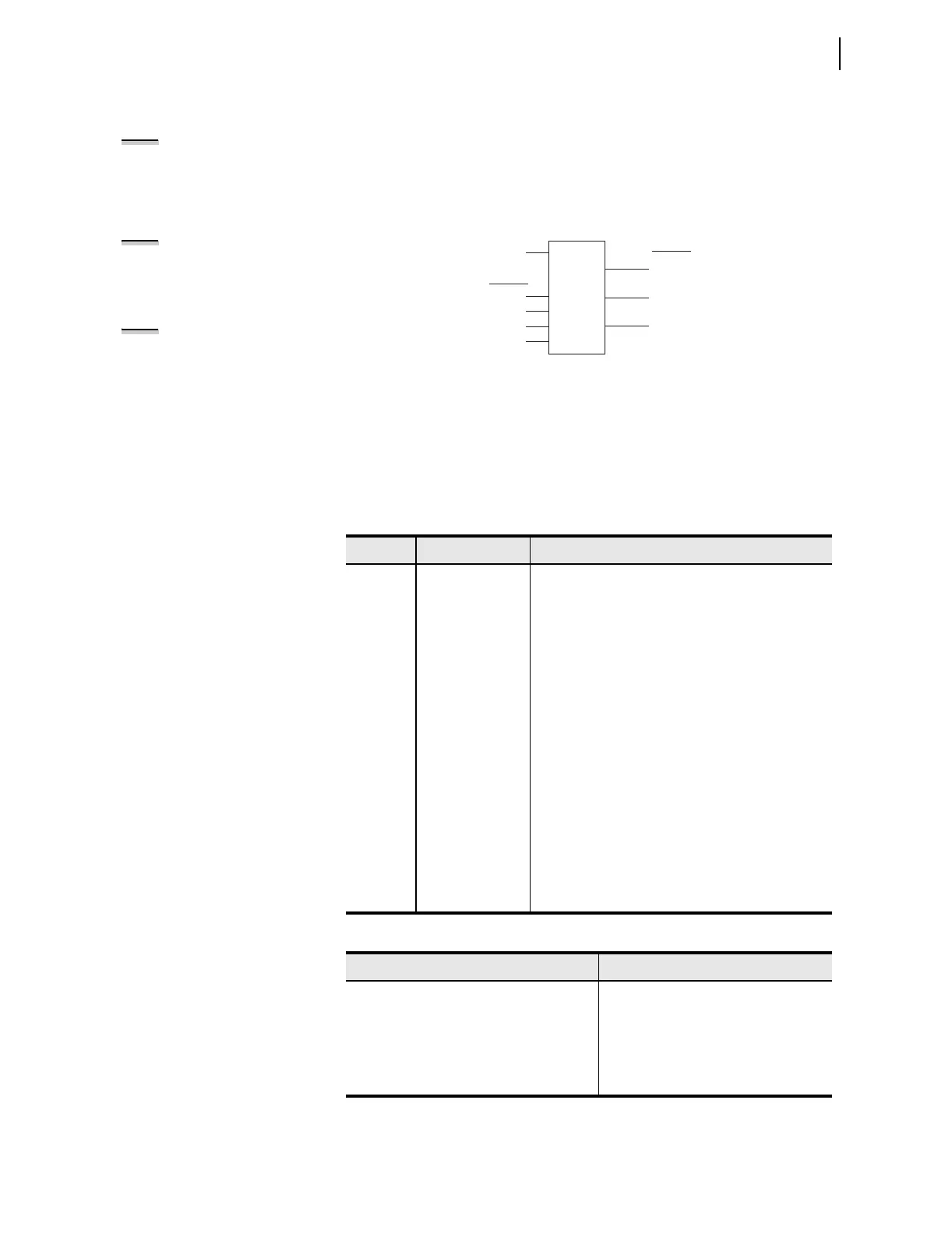
Each counter element consists of one count setting, four control inputs, two
digital outputs, and one analog output. Figure 4.48 shows Counter 01, the first
of 32 counters available in the device.
Figure 4.48 Counter 01
Digital output SC01QD asserts when the counter is at position zero, and
Digital output SC01QU asserts when the counter reaches the programmable
count value. Use the reset input (SC01R) to force the count to zero, and the
analog output (SCnn) with analog comparison operators. Tab le 4.36 describes
the counter inputs and outputs, and Table 4.37 shows the order of precedence
of the control inputs.
Table 4.36 Counter Input/Output Description
Name Type Description
SCnnLD Active High Input Load counter with the preset value to assert the output
(SCnQU) (follows SELOGIC setting).
SCnnPV Input Value This Preset Value is loaded when SCnLD pulsed. This
Preset Value is the number of counts before the output
(SCnQU) asserts (follows SEL
OGIC setting).
SCnnCU Rising-Edge Input Count Up increments the counter (follows SEL
OGIC
setting).
SCnnCD Rising-Edge Input Count Down decrements the counter (follows SEL-
OGIC setting).
SCnnR Active High Input Reset counter to zero (follows SEL
OGIC setting)
SCnnQU Active High Out-
put
This Q Up output asserts when the Preset Value (maxi-
mum count) is reached (SCn = SCnPV, n = 01 to 32).
SCnnQD Active High Out-
put
This Q Down output asserts when the counter is equal
to zero (SCn = 0, n = 01 to 32).
SCnn Output Value This counter output is an analog value that may be
used with analog comparison operators in a SEL
OGIC
control equation and viewed using the COU com-
mand.
Table 4.37 Order of Precedence of the Control Inputs
Order Input
1SCnnR
2SCnnLD
3SCnnCU
4SCnnCD
NOTE: These counter elements
conform to the standard counter
function block #3 in IEC 1131-3 First
Edition 1993-03 International
Standard for Programmable
controllers—Part 3: Programming
languages.
NOTE: For device configurations that
include either current or voltage
cards, the SEL-751A tracks the
frequency. When tracking the
frequency, the processing interval
varies with the frequency.
NOTE: If setting SCnnCD is set to NA,
the entire counter nn is disabled).
SC01PV
SC01R
SC01LD
SC01CU
SC01CD
Counter 01
SC01QU
SC01QD
SC01
SEL
OGIC
Output