4.11
Date Code 20100129 Instruction Manual SEL-751A Relay
Protection and Logic Functions
Basic Protection
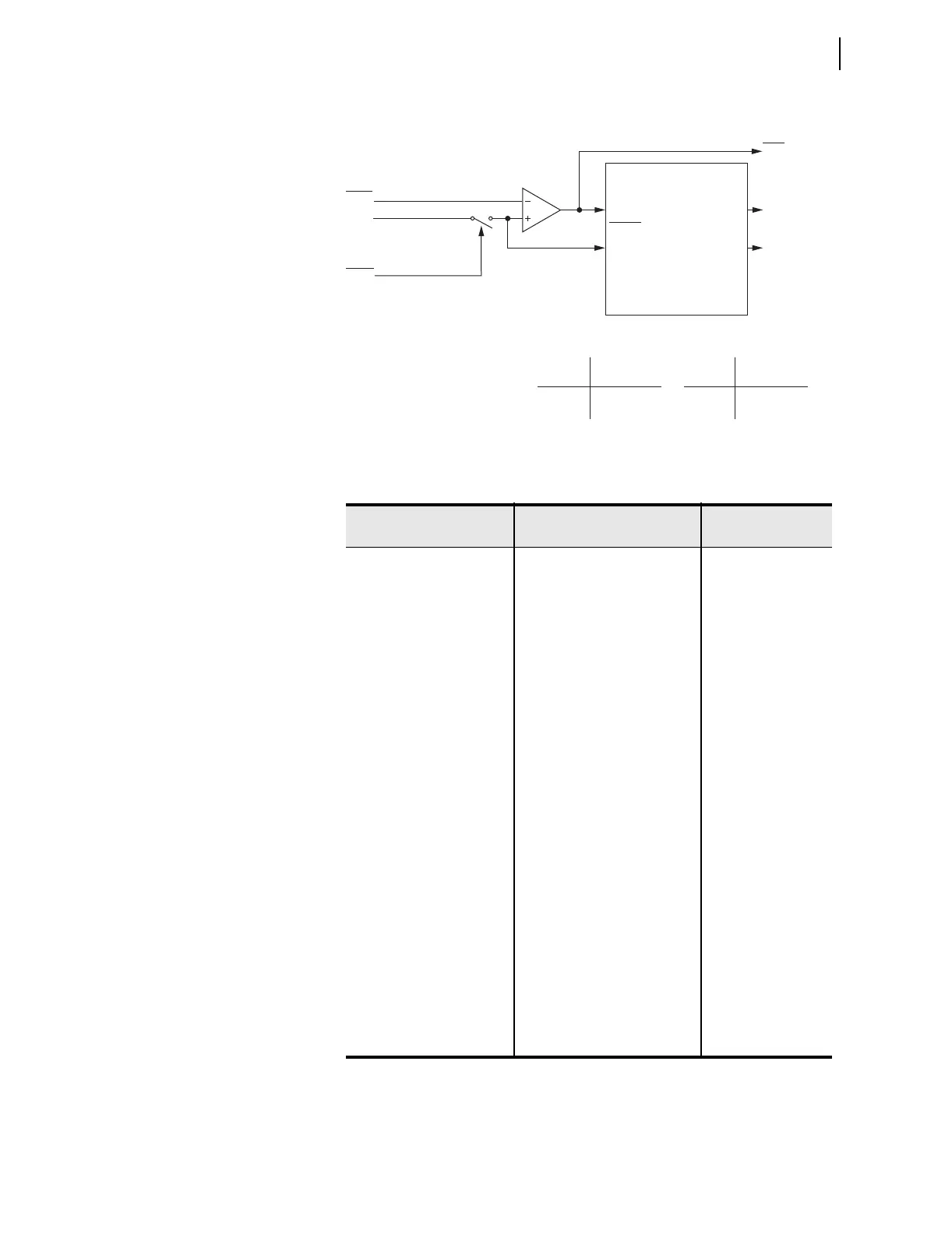
Figure 4.3 Phase Time-Overcurrent Elements 51AT, 51BT, and 51CT
Table 4.9 Maximum Phase Time-Overcurrent
Setting Prompt Setting Range
Setting Name :=
Factory Defau lt
TOC TRIP LVL OFF, 0.50–16.00 A
a
,
0.10–3.20 A
b
a
For I
NOM
= 5 A.
b
For I
NOM
= 1 A.
51P1P := 6.00
51P1P := 1.2
TOC CURVE SEL U1, U2, U3, U4, U5, C1, C2,
C3, C4, C5
51P1C := U3
TOC TIME DIAL 0.50–15.00
c
,
0.05–1.00
d
c
For 51_C := U_ .
d
For 51_C := C_.
51P1TD := 3.00
EM RESET DELAY Y, N 51P1RS := N
CONST TIME ADDER 0.00–1.00 sec 51P1CT := 0.00
MIN RESPONSE TIM 0.00–1.00 51P1MR := 0.00
TOC TRQ CONTROL SEL
OGIC 51P1TC := 1
TOC TRIP LVL OFF, 0.50–16.00 A
a
,
0.10–3.20 A
b
51P2P := 6.00
51P2P := 1.2
TOC CURVE SEL U1, U2, U3, U4, U5, C1, C2,
C3, C4, C5
51P2C := U3
TOC TIME DIAL 0.50–15.00
c
,
0.05–1.00
d
51P2TD := 3.00
EM RESET DELAY Y, N 51P2RS := N
CONST TIME ADDER 0.00–1.00 sec 51P2CT := 0.00
MIN RESPONSE TIM 0.00–1.00 51P2MR := 0.00
TOC TRQ CONTROL SEL
OGIC 51P2TC := 1
51AP
|IA|
Setting
51ATC
Torque Control Switch
SELOGIC
Torque Control
Pickup
Curve
Timeout
Reset
51AP
51AR
51AT
51ATC Torque Control
State Switch Position
Logical 1 Closed
Logical 0 Open
Setting
51ARS = Reset Timing
Y Electromechanical
N 1 Cycle
Relay
Word
Bits
SELOGIC
Setting
51AT Phase
Time-Overcurrent Element
Curve Timing and Reset Timing
Settings
51AP Pickup
51AC Curve Type
51ATD Time Dial
51ARS Electromechanical
Reset? (Y/N)
51ACT Const. Time Add.
51AMR Min. Response
(From Figure 4.1)
Logic State of 51ATC Controls the Torque Control Switch
Note: 51AT element shown above; 51BT and 51CT are similar.