2.25
Date Code 20100129 Instruction Manual SEL-751A Relay
Installation
AC/DC Control Connection Diagrams
The fast bus trip scheme is often referred to as a reverse-interlocking or zone-interlocking scheme.
Voltage option is needed for voltage elements, synchronism-check elements, and metering (e.g., voltage, KW, KVAR).
INxxx and OUTxxx indicate user-configurable optional digital inputs and outputs. Voltage channel VS is shown connected
for use in voltage and synchronism-check elements and voltage metering. The VS voltage channel can be used for other
voltage input such as 3VO from a broken delta PT connection as long as care is taken to disable the synchronism-check
elements.
Channel IN provides current I
N
for the neutral ground overcurrent elements. Separate from Channel IN, the residual
ground overcurrent elements operate from the internally derived residual current I
G
(I
G
= 3I
0
= I
A
+ I
B
+ I
C
). But in this
residual connection example, the neutral ground and residual ground overcurrent elements operate the same because
I
N
= I
G
.
Although automatic reclosing is probably not needed in this example, output contact OUT102 can close the ciruit breaker
via initiation from various means (serial port communications, optoisolated input assertion, etc.) with desired
supervision (e.g., synchronism check).
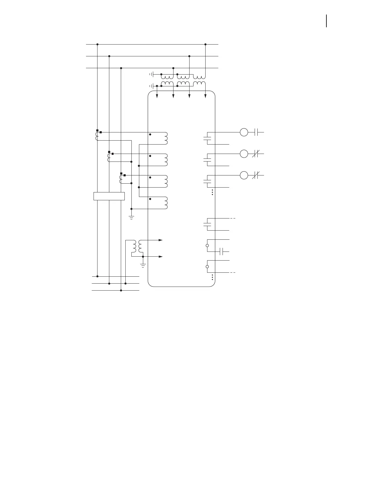
Figure 2.21 SEL-751A Provides Overcurrent Protection for a Distribution Bus (Includes Fast Bus Trip Scheme)
(Wye-Connected PTs)
TC
Trip
Coil
52A
(+)
(—)
Trip
Circuit
IA
C
B
A
SEL-751A RELAY
OUT103
CC
Close
Coil
52B
(+)
(—)
Close
Circuit
IB OUT102
86
Lock
Out
86B
(+)
(—)
Breaker
Failure
Trip
Circuit
IC OUTxxx
IN
BUS
52
(+)
52A
to Annunciator, RTU,
or SEL-2032/2030/2020
From Feeder Relays
(Fast Bus Trip Scheme)
ALARM
OUT101
(+)
(—)
Breaker Status
INxxx
(—)
INxxx
VCNVBVA
VS
NS
A
B
C