2.33
Date Code 20100129 Instruction Manual SEL-751A Relay
Installation
Arc-Flash Protection: System Installation
Bare-Fiber Sensor
Installation
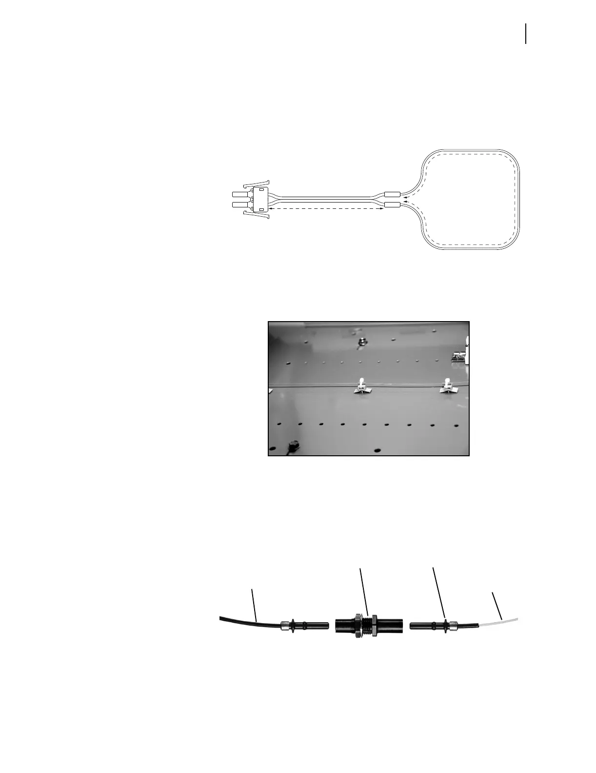
The bare-fiber sensor is optimized for monitoring of large distributed
resources, such as switchgear system bus enclosures. The bare-fiber sensor is
omnidirectional and can be mounted in close proximity to the switchgear
enclosure walls. Figure 2.33 shows a schematic diagram of the bare-fiber
sensor. Figure 2.34 shows a bare-fiber sensor mounting example photo.
Total loop length = 2 • A + B (allowed range 3 to 70 meters)
Range for A: 1 to 30 meters
Range for B: 1 to 50 meters
Figure 2.33 Bare-Fiber Sensor Assembly
Figure 2.34 Bare-Fiber Sensor Mounting Example
A bare-fiber sensor consists of the major components shown in Figure 2.35.
Two connector options (V-pin and ST) are available for transitioning from the
jacketed to the bare-fiber section as shown in Figure 2.36. The ST connector
option is generally superior because of positive locking and lower coupling
loss.
Figure 2.35 Bare-Fiber Sensor Components (V-Pin Style)
For correct operation, a bare-fiber sensor must be located within 2 m of the
arcing site, with at least 0.5 m of the fiber exposed to the light. The maximum
length of the bare-fiber sensor is limited to 70 m and includes both, bare- and
i8004a
Dual V-Pin
Latch
V-Pin
Terminators
V-Pin or
ST Splice
Connector
“A” Meters
“B” Meters
Bare-Fiber
Jacketed-Fiber Zipcord Duplex
Bare-Fiber Sen-
sor Section
Bare-Fiber Transition
Connectors (V-Pin)
Connector Splice
Bushing (V-Pin)
Jacketed-Fiber
Section