7.8
SEL-751A Relay Instruction Manual Date Code 20100129
Communications
Communications Interfaces
+5 Vdc Power Supply
Serial port power can provide as much as 0.5 A total from all of the +5 Vdc
pins. Some SEL communications devices require the +5 Vdc power supply.
This +5 Vdc is available in any combination of Pins 1, 3, and 7 without the
need for hardware jumpers.
Connect Your
PC to the Relay
The front port of the SEL-751A is a standard female 9-pin connector with pin
numbering shown in Figure 7.9. The pinout assignments for this port are
shown in Table 7.2. You can connect to a standard 9-pin computer port with
SEL Cable C234A; wiring for this cable is shown in Figure 7.10. SEL Cable
C234A and other cables are available from SEL. Use the SEL-5801 Cable
SELector software to select an appropriate cable for another application. This
software is available for free download from the SEL website at
www.selinc.com.
For best performance, SEL Cable C234A should not be more than 15 meters
(50 feet) long. For long-distance communications and for electrical isolation
of communications ports, use the SEL family of fiber-optic transceivers.
Contact SEL for more details on these devices.
Port Connector and
Communications
Cables
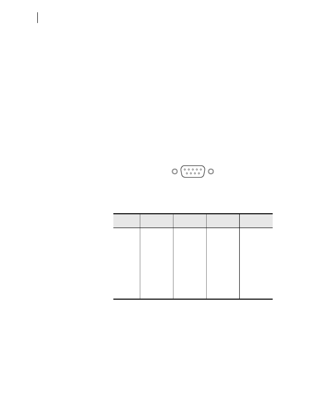
Figure 7.9 shows the front-panel EIA-232 serial port (PORT F) DB-9 connector
pinout for the SEL-751A.
Figure 7.9 EIA-232 DB-9 Connector Pin Numbers
Table 7.2 shows the pin functions for the EIA-232 and EIA-485 serial ports.
The following cable diagrams show several types of EIA-232 serial
communications cables that connect the SEL-751A to other devices. These
and other cables are available from SEL. Contact the factory for more
information.
Table 7.2 EIA-232/EIA-485 Serial Port Pin Functions
Pin
a
a
For EIA-485, the pin numbers represent relay terminals CO1 through C05 Port 3 (EIA-485)
pin-out is similar).
PORT 3
EIA-232
PORT 4C
EIA-232
PORT 4A
EIA-485
a
PORT F
EIA-232
1 +5 Vdc +5 Vdc +TX N/C
2 RXD RXD, RX –TX RXD
3 TXD TXD, TX +RX TXD
4IRIG+
b
b
See Models, Options, and Accessories on page 1.12 for availability of IRIG-B.
N/C –RX N/C
5 GND GND Shield GND
6IRIG–
b
N/C N/C
7 RTS RTS RTS
8 CTS CTS CTS
9 GND GND GND
5 4 3 2 1
9 8 7 6