2.12
SEL-751A Relay Instruction Manual Date Code 20100129
Installation
I/O Configuration
Password, Breaker
Control, and SELBOOT
Jumper Selection
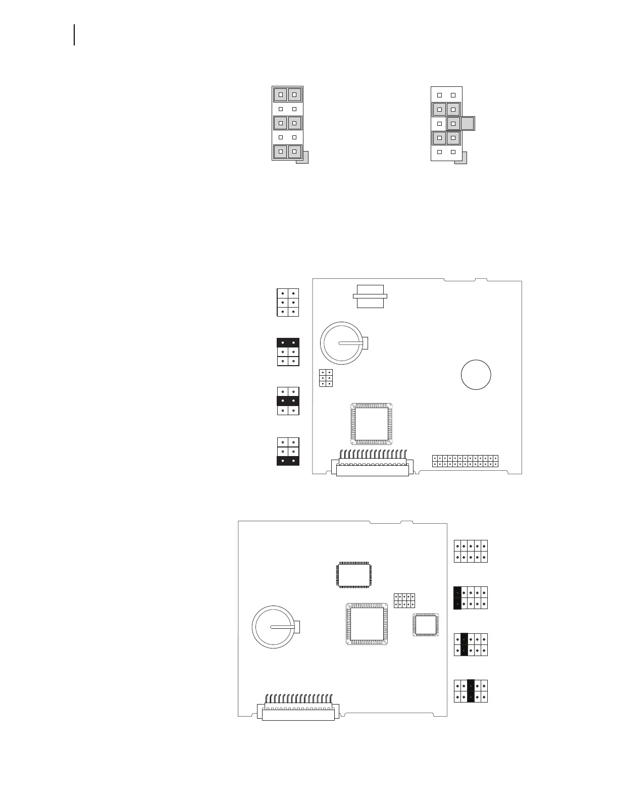
Figure 2.7 shows the major components of the B-slot card in the base unit.
Notice the three sets of pins labeled A, B, and C.
Figure 2.7 Pins for Password, Breaker Control, and SELBOOT Jumper
Figure 2.5 Current Output Jumpers Figure 2.6 Voltage Output
Jumpers
9
5
1
10
6
2
JMP4
JMP4 Selected as Current Output
7
5
3
8
6
4
JMP1
JMP1 Selected as Voltage Output
JMP1
ABC
JMP1
ABC
JMP1
ABC
JMP1
ABC
Password
Bypassed
Default
Positions
SEL
BOOT
Forced
Remote
Breaker
Control
Allowed
JMP1
Card Layout for Relays With Firmware Versions R400 and Later
Card Layout for Relays With Firmware Versions Earlier Than R400
A
B
C
JMP1
A
B
C
JMP1
A
B
C
JMP1
Default
Positions
Password
Bypassed
Remote
Breaker
Control
Allowed
A
B
C
JMP1
SEL
BOOT
Forced
A
B
C
JMP1
A B C