4.44
SEL-751A Relay Instruction Manual Date Code 20100129
Protection and Logic Functions
Voltage-Based Protection
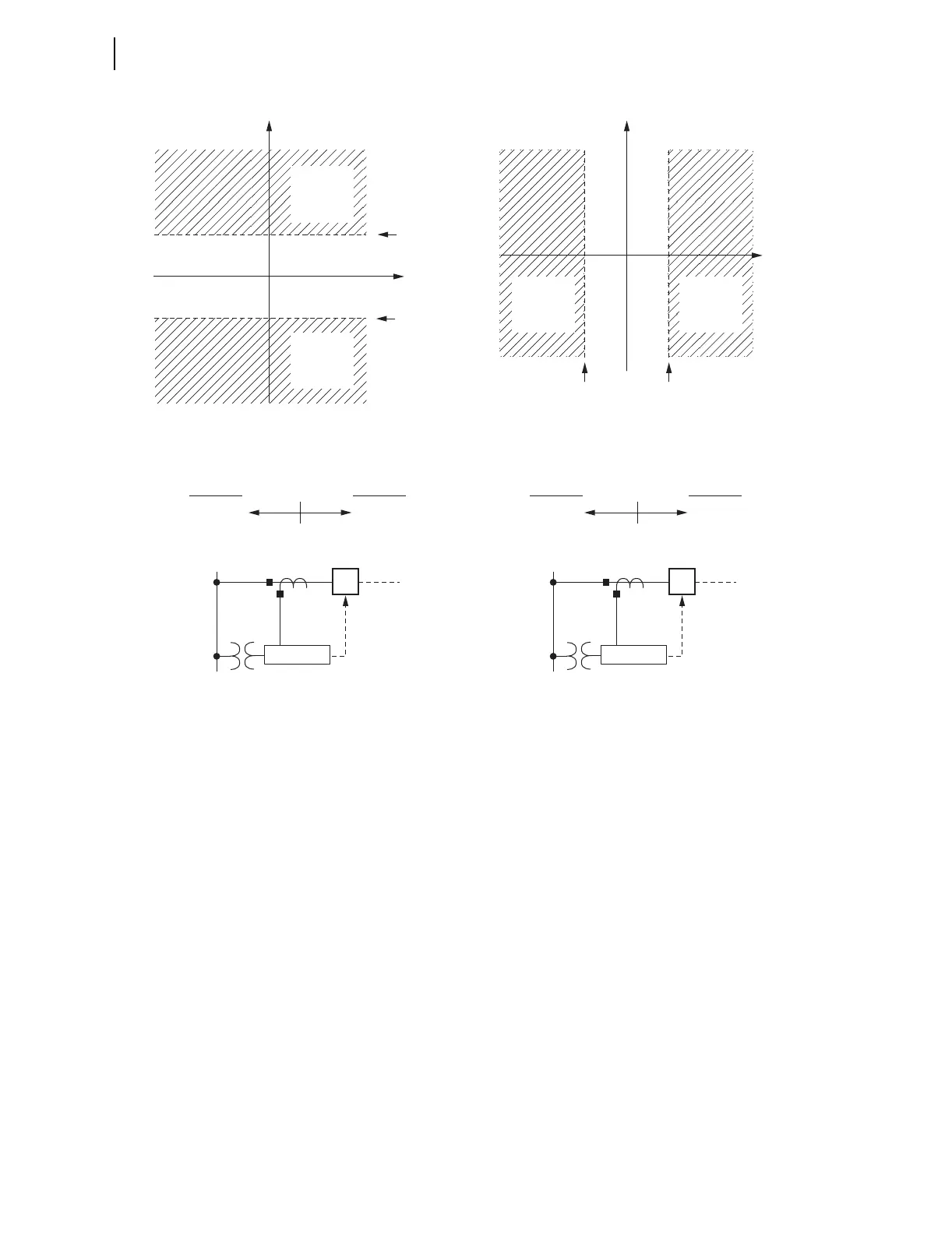
Figure 4.24 Power Elements Operation in the Real/Reactive Power Plane
The power element type settings are made in reference to the load convention:
➤ +WATTS: positive or forward real power
➤ –WATTS: negative or reverse real power
➤ +VARS: positive or forward reactive power
➤ –VARS: negative or reverse reactive power
The two power element time delay settings (PWR1D and PWR2D) can be set
to have no intentional delay for testing purposes. For protection applications
involving the power element Relay Word bits, SEL recommends a minimum
time delay setting of 0.1 second for general applications. The classical power
calculation is a product of voltage and current, to determine the real and
reactive power quantities. During a system disturbance, because of the high
sensitivity of the power elements, the changing system phase angles and/or
frequency shifts may cause transient errors in the power calculation.
Reactive
Power
Reactive
Power
Real
Power
Real
Power
3PWR2P
(pickup)
3PWR1P
(pickup)
3PWR1P
(pickup)
3PWR2P
(pickup)
Set as Reactive Power Elements
Reverse
(Leading)
3PWR2
3PWR1
3PWR2 3PWR1
Forward
(Lagging)
Set as Real Power Elements
Reverse
Forward
SEL-751A
52
SEL-751A
52
PWR1T =
+VARS
(type)
PWR2T =
—VARS
(type)
PWR2T =
—WATTS
(type)
PWR1T =
+WATTS
(type)
Note: Highlighted area represents pickup region