7.9
Date Code 20100129 Instruction Manual SEL-751A Relay
Communications
Communications Interfaces
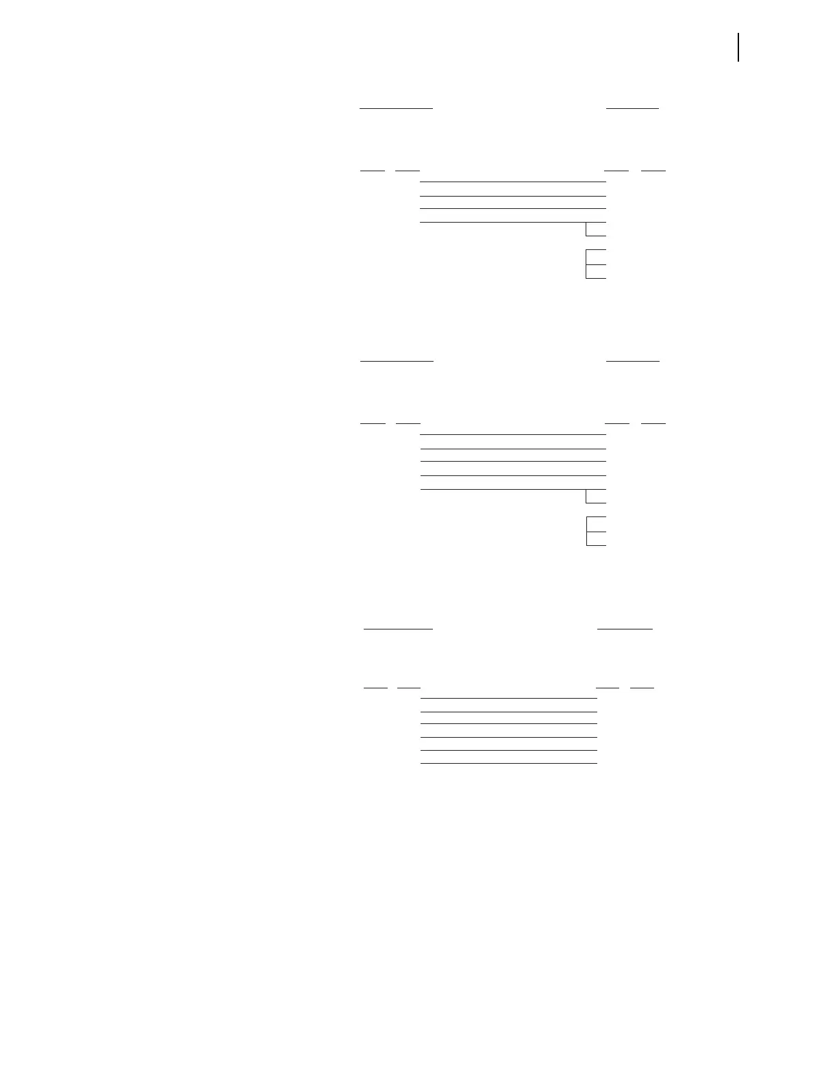
Figure 7.10 SEL Cable C234A—SEL-751A to DTE Device
Figure 7.11 SEL Cable C227A—SEL-751A to DTE Device
Figure 7.12 SEL Cable C222—SEL-751A to Modem
SEL-751A Relay
9-Pin Male
D Subconnector
9-Pin Female
D Subconnector
2
3
5
8
3
2
5
8
7
1
4
6
RXD
TXD
GND
CTS
TXD
RXD
GND
CTS
RTS
DCD
DTR
DSR
Pin
Func.
Pin
Func.
Pin # Pin #
*DTE Device
*DTE = Data Terminal E
ui
ment (Com
uter, Terminal, etc.)
SEL-751A Relay
9-Pin Male
D Subconnector
25-Pin Female
D Subconnector
5
3
2
9
8
7
3
2
1
4
5
6
8
20
GND
TXD
RXD
GND
CTS
GND
RXD
TXD
GND
RTS
CTS
DSR
DCD
DTR
Pin
Func.
Pin
Func.
Pin # Pin #
*DTE Device
*DTE = Data Terminal Equipment (Computer, Terminal, etc.)
SEL-751A Relay
9-Pin Male
D Subconnector
25-Pin Female
D Subconnector
5
3
7
2
8
9
7
2
20
3
8
1
GND
TXD
RTS
RXD
CTS
GND
GND
TXD (IN)
DTR (IN)
RXD (OUT)
CD (OUT)
GND
Pin
Func.
Pin
Func.
Pin # Pin #
**DCE Device
**DCE = Data Communications E
ui
ment (Modem, etc.)