10.8
SEL-751A Relay Instruction Manual Date Code 20100129
Testing and Troubleshooting
Commissioning Tests
Delta-Connected Voltages
Perform the following steps to test delta-connected voltages:
Step 1. Connect the current source to the relay, as shown in
Figure 10.3.
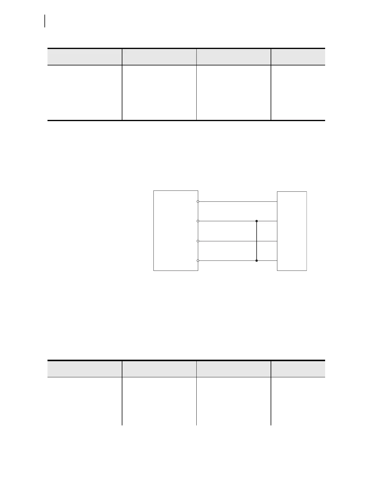
Step 2. Connect the voltage source to the relay, as shown in
Figure 10.5. Make sure that DELTA_Y := DELTA.
Figure 10.5 Delta Voltage Source Connections
Step 3. Using the front-panel SET/SHOW or the serial port SHOW
command, record the CTR, PTR, and PHROT setting values.
Step 4. Apply the current and voltage quantities shown in Column 1 of
Table 10.5.
Values are given for PHROT := ABC and PHROT := ACB.
Step 5. Use the front-panel
METER or the serial port MET command to
verify the results.
PHROT := ACB
Ia = 2.5 ∠−26
Ib = 2.5 ∠+94
Ic = 2.5 ∠−146
Expected:
P = 0.4523 • CTR • PTR
Expected:
Q = 0.2211 • CTR • PTR
Expected:
pf = 0.90 lag
Va = 6 7 ∠0
Vb = 67 ∠+120
Vc = 67 ∠−120
Measured: Measured: Measured:
Table 10.4 Power Quantity Accuracy—Wye Voltages (Sheet 2 of 2)
Applied Currents and Voltages
Real Power
(kW)
Reactive Power (kVAR)
Power Factor
(pf)
SEL-751A
E01
E02
E03
E04
Voltage
Test
Source
VA
VB
VC
VN
Table 10.5 Power Quantity Accuracy—Delta Voltages (Sheet 1 of 2)
Applied Currents and Voltages
Real Power
(kW)
Reactive Power
(kVAR)
Power Factor
(pf)
PHROT := ABC
Ia = 2.5 ∠–26
Ib = 2.5 ∠–146
Ic = 2.5 ∠+94
Expected:
P = 0.4677 • CTR • PTR
Expected:
Q = 0.2286 • CTR • PTR
Expected
pf = 0.90 lag
Vab = 120 ∠+30
Vbc = 120 ∠–90
Measured: Measured: Measured: