Date Code 20100129 Instruction Manual SEL-751A Relay
Appendix J
Relay Word Bits
Overview
The protection and control element results are represented by Relay Word bits
in the SEL-751A Feeder Protection Relay. Each Relay Word bit has a label
name and can be in either of the following states:
➤ 1 (logical 1)
➤ 0 (logical 0)
Logical 1 represents an element being picked up or otherwise asserted.
Logical 0 represents an element being dropped out or otherwise deasserted.
Table J.1 and Tab le J.2 show a list of Relay Word bits and corresponding
descriptions. The Relay Word bit row numbers correspond to the row numbers
used in the TAR command (see TARGET Command (Display Relay Word Bit
Status) on page 7.41).
Any Relay Word bit (except Row 0) can be used in SEL
OGIC
®
control
equations (see Section 4: Protection and Logic Functions) and the Sequential
Events Recorder (SER) trigger list settings (see Section 9: Analyzing Events).
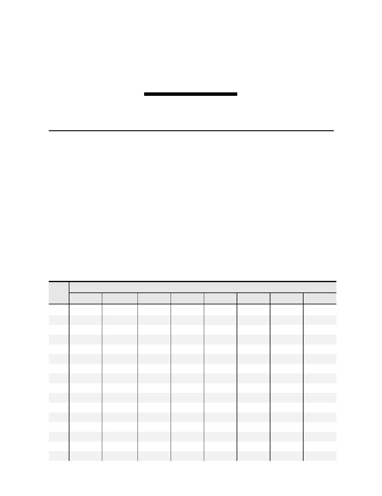
Ta b le J . 1 S E L-7 5 1 A Re l ay Wo rd B i t s (Sheet 1 of 4)
Bit/
Row
Relay Word Bits
7 6 5 4 3 2 1 0
TAR 0
ENABLED TRIP_LED TLED_01 TLED_02 TLED_03 TLED_04 TLED_05 TLED_06
1
50A1P 50B1P 50C1P 50PAF ORED50T ORED51T 50NAF 52A
2
50P1P 50P2P 50P3P 50P4P 50Q1P 50Q2P 50Q3P 50Q4P
3
50P1T 50P2T 50P3T 50P4T 50Q1T 50Q2T 50Q3T 50Q4T
4
50N1P 50N2P 50N3P 50N4P 50G1P 50G2P 50G3P 50G4P
5
50N1T 50N2T 50N3T 50N4T 50G1T 50G2T 50G3T 50G4T
6
51AP 51BP 51CP 51P1P 51P2P 51N1P 51N2P 51QP
7
51AT 51BT 51CT 51P1T 51P2T 51N1T 51N2T 51QT
8
51AR 51BR 51CR 51P1R 51P2R 51N1R 51N2R 51QR
9
51G1P 51G1T 51G1R 51G2P 51G2T 51G2R 27P1 27P1T
10
27P2 27P2T 59P1 59P1T 59P2 59P2T 3P59 3P27
11
81D1T 81D2T 81D3T 81D4T 81D5T 81D6T 55A 55T
12
AMBALRM AMBTRIP OTHALRM OTHTRIP BKMON * BFI BFT
13
LINKA LINKB PMDOK SALARM WA R NI N G TSOK IRIGOK FAULT
14
COMMIDLE COMMLOSS REMTRIP COMMFLT CFGFLT 3PWR1T 3PWR2T LOP
15
TRIP OUT101 OUT102 OUT103 OUT301 OUT302 OUT303 OUT304