4.49
Date Code 20100129 Instruction Manual SEL-751A Relay
Protection and Logic Functions
Rate-of-Change of Frequency Protection
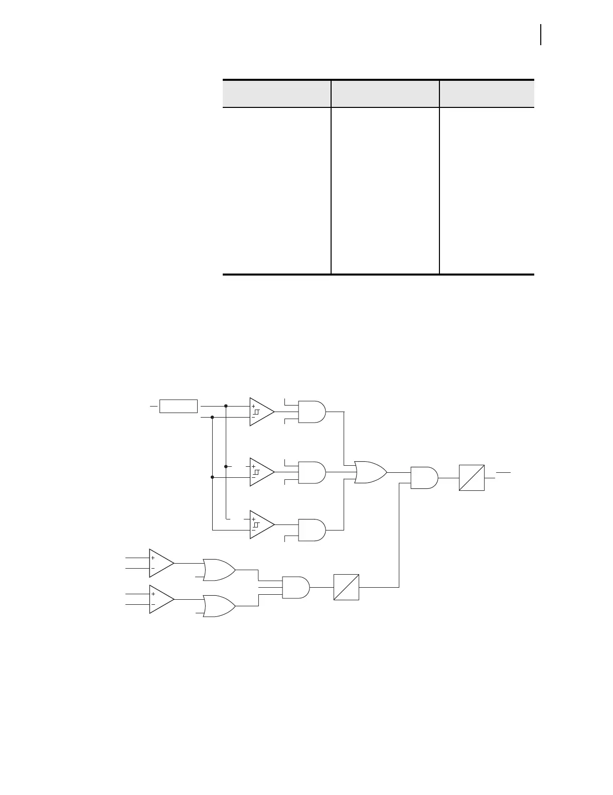
Use E81R setting to enable number of the elements desired, Figure 4.28
shows the element logic. The SEL-751A measures frequency (mf1) and
second frequency (mf2) after a time window (dt) determined by Trip Level
setting (81RnTP). Hysteresis is such that pickup is 100% of 81RnTP setting
and dropout is 95%. Table 4.24 shows the time windows for different trip level
settings.
Figure 4.28 81R Frequency Rate-of-Change Scheme Logic
81R2 DO DELAY 0.00–60.00 sec 81R2DO := 0.00
81R3 TRIP LEVEL OFF, 0.10–15.00 81R3TP := OFF
81R3 TREND INC, DEC, ABS 81R3TRND := ABS
81R3 TRIP DELAY 0.10–60.00 sec 81R3TD := 1.00
81R3 DO DELAY 0.00–60.00 sec 81R3DO := 0.00
81R4 TRIP LEVEL OFF, 0.10–15.00 81R4TP := OFF
81R4 TREND INC, DEC, ABS 81R4TRND := ABS
81R4 TRIP DELAY 0.10–60.00 sec 81R4TD := 1.00
81R4 DO DELAY 0.00–60.00 sec 81R4DO := 0.00
a
See Note on page U.4.30 for explanation of Vnm.
b
I
NOM
is nominal rating of the phase CTs (1A or 5A).
Table 4.23 Rate-of-Change-of-Frequency Settings (Sheet 2 of 2)
Setting Prompt Setting Range
Setting Name :=
Factory D efault
Setting 81RnTp
where n = 1–4
Frequency
81RnTRND = INC
81RnTRND = ABS
81RnTRND = DEC
mf2 > FNOM
mf2 < FNOM
FREQTRK
81RVSUP = OFF
81RISUP = OFF
V1
I1
81RVSUP
81RISUP
PU = 81RnTD
DO = 81RnDO
3 SEC
0
(mf2–mf1)/dt
PU
DO
81RnT
Relay
Word
Bit
95%
95%
95%
ABS
*(-1)