I.3
Date Code 20100129 Instruction Manual SEL-751A Relay
MIRRORED BITS Communications
Operation
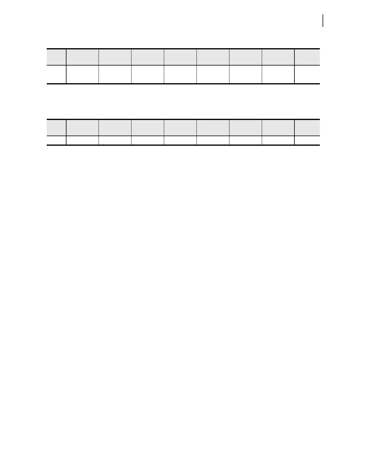
Table I.3 shows an example of the values of the MIRRORED BITS for a
RXDFLT setting of 10100111.
Individual pickup and dropout security counters supervise the movement of
each received data bit into the corresponding RMBn element. You can set each
pickup/dropout security counter from 1 to 8. A setting of 1 causes a security
counter to pass every occurrence, while a setting of 8 causes a counter to wait
for eight consecutive occurrences in the received data before updating the data
bits. The pickup and dropout security count settings are separate. Control the
security count settings with the settings RMBnPU and RMBnDO.
A pickup/dropout security counter operates identically to a pickup/dropout
timer, except that the counter uses units of counted received messages instead
of time. Select a setting for the security counter in accordance with the
transmission rate (see Table I.1). For example, when transmitting at 2400
baud, a security counter set to 2 counts delays a bit by about 30 ms. However,
when operating at 9600 baud, a setting of 2 counts delays a bit by about
8.5 ms.
You must consider the impact of the security counter settings in the receiving
relay to determine the channel timing performance, particularly when two
relays of different processing rates are communicating via M
IRRORED BITS,
such as an SEL-321 and an SEL-751A. The SEL-321 processes power system
information each 1/8 power system cycle, but, when transmitting at 19200
baud, the SEL-751A processes M
IRRORED BITS messages at 4.15 ms at 60 Hz
(4 times per power system cycle at 60 Hz). Although the SEL-321 processes
power system information each 1/8 power system cycle, the relay processes
the M
IRRORED BITS pickup/dropout security counters as MIRRORED BITS
messages are received. Because the SEL-751A transmits messages at
approximately 1/4-cycle processing interval (9600 baud and above, see
Table I.1), a counter set to two in the SEL-321 delays a received bit by another
approximately 1/2 cycle. However, a security counter in the SEL-751A with a
setting of two delays a received bit from the SEL-321 by 1/4 cycle, because
the SEL-751A is receiving new M
IRRORED BITS messages each 1/8 cycle
from the SEL-321.
Channel
Synchronization
When an SEL-751A detects a communications error, it deasserts ROKA or
ROKB. If an SEL-751A detects two consecutive communications errors, it
transmits an attention message, which includes the TXID setting. The relay
transmits an attention message until it receives an attention message that
includes a match to the TXID setting value. If the attention message is
successful, the relay has properly synchronized and data transmission
resumes. If the attention message is not successful, the relay repeats the
attention message until it is successful.
Table I.2 Positions of the MIRRORED BITS
Bit/
Row
7 6 5 4 3 2 1 0
88
RMB8A RMB7A RMB6A RMB5A RMB4A RMB3A RMB2A RMB1A
90
RMB8B RMB7B RMB6B RMB5B RMB4B RMB3B RMB2B RMB1B
Ta b le I .3 M IRRORED BITS Values for a RXDFLT Setting of 10100111
Bit/
Row
7 6 5 4 3 2 1 0
88
10100111