5.12
SEL-751A Relay Instruction Manual Date Code 20100129
Metering and Monitoring
Station DC Battery Monitor
DC Under- and
Overvoltage
Elements
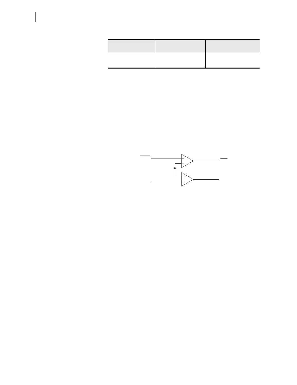
Refer to Figure 5.15. The station dc battery monitor compares the measured
station battery voltage (Vdc) to the undervoltage (low) and overvoltage (high)
pickups DCLOP and DCHIP. The setting range for pickup settings DCLOP
and DCHIP is:
20 to 300 Vdc, 0.01Vdc increments
This range allows the SEL-751A to monitor nominal battery voltages of 24,
48, 110, 125, 220, and 250V. When testing the pickup settings DCLOP and
DCHIP, do not operate the SEL-751A outside of its power supply limits. See
Specifications: General on page 1.20 for the various power supply
specifications. The power supply rating is located on the serial number sticker
on the relay side panel.
Figure 5.15 DC Under- and Overvoltage Elements
Logic outputs DCLO and DCHI in Figure 5.15 operate as follows:
Create Desired Logic
for DC Under- and
Overvoltage Alarming
Pickup settings DCLOP and DCHIP are set independently. Thus, they can be
set:
DCLOP < DCHIP or DCLOP > DCHIP
Figure 5.16 shows the resultant dc voltage elements that can be created with
SEL
OGIC control equations for these two setting cases. In these two examples,
the resultant dc voltage elements are time-qualified by timer SVnT and then
routed to output contact OUTxxx for alarm purposes.
Table 5.8 Station DC Battery Monitor Settings
Setting Prompt Setting Range
Setting Name :=
Facto ry Defau lt
DC UNDER VOLT PU (OFF, 20.00-300.00) Vdc DCLOP := OFF
DC OVER VOLT PU (OFF, 20.00-300.00) Vdc DCHIP := OFF
DCLO = 1 (logical 1), if Vdc ≤ pickup setting DCLOP
= 0 (logical 0), if Vdc > pickup setting DCLOP
DCHI = 1 (logical 1), if Vdc ≥ pickup setting DCHIP
= 0 (logical 0), if Vdc < pickup setting DCHIP
DCLO
DCHI
Vdc
Relay
Word
Bits
DCLOP
DCHIP
Settings
Undervoltage
Overvoltage
(From Rear- Panel
Terminals Labeled
VBAT+ and VBAT—)