7.4
SEL-751A Relay Instruction Manual Date Code 20100129
Communications
Communications Interfaces
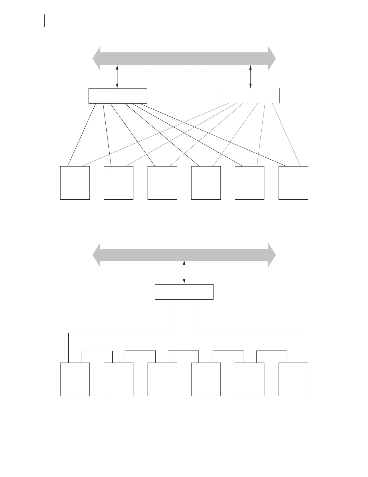
Figure 7.2 Ethernet Network Configuration With Dual Redundant Connections (Failover Mode)
Figure 7.3 Ethernet Network Configuration With Ring Structure (Switched Mode)
SEL-710
SEL-787SEL-710SEL-751A SEL-751A SEL-751A
NETWORK
Ethernet Switch B
Ethernet Switch A
CAT 5 shielded twisted pair (STP) cables with
RJ-45 connectors (SEL-C627/C628) for
copper Ethernet ports
OR
Fiber-optic Ethernet cables with
LC connectors (SEL-C807) for
fiber-optic Ethernet ports
1A 1B 1B 1B1B1B1B 1A1A1A1A1A
Set Port 1 (Ethernet) settings in each relay. For relays with
single Ethernet ports, specify copper or fiber-optic network.
SEL-710
SEL-787SEL-710SEL-751A SEL-751A SEL-751A
Ethernet Switch (Managed)
NETWORK
Set Port 1 (Ethernet) settings in each relay. For relays with
single Ethernet ports, specify copper or fiber-optic network.
CAT 5 shielded twisted pair (STP) cables with
RJ-45 connectors (SEL-C627/C628) for
copper Ethernet ports
OR
Fiber-optic Ethernet cables with
LC connectors (SEL-C807) for
fiber-optic Ethernet ports
1B 1B1B1B1B 1B1A 1A 1A 1A 1A 1A