4.97
Date Code 20100129 Instruction Manual SEL-751A Relay
Protection and Logic Functions
Arc-Flash Protection
The default processing interval in the SEL-751A is ¼ of the power system
cycle. However, to obtain a faster arc-flash protection you can select two
outputs that will be processed every 1/16 of a power system cycle. Use the
setting AOUTSLOT to select these outputs. For instance, if slot 3 is selected
(AOUTSLOT := 301_2) the SEL
OGIC equations OUT301 and OUT302 will
be processed at the 1/16 of a cycle rate. In order to get the fastest possible
operate time use the contacts selected by the AOUTSLOT setting for tripping.
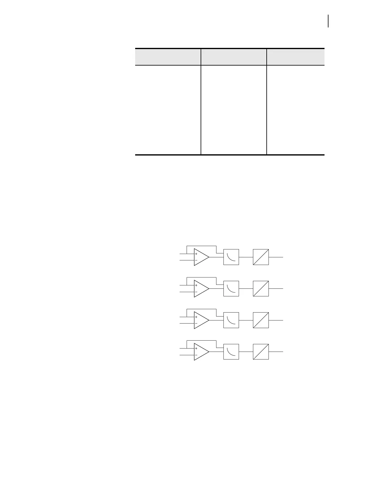
Figure 4.53 shows the TOL element logic diagram.
Figure 4.53 Inverse Time-Overlight Element Logic
Figure 4.54 shows the inverse time-overlight element curve shape. The
element uses 32 samples per cycle data, processed 16 times per cycle. TOL
element algorithm ensures that the light must be present for a minimum of two
samples, regardless of the light level. It also ensures that for low light levels,
element operation cannot be delayed for more than ¼ of a power system cycle.
TOL 2 PICKUP 3.0–20.0 %
a
0.6–4.0 %
b
TOL2P := 5.0
SENSOR 3 TYPE NONE, POINT, FIBER AFSENS3 := NONE
TOL 3 PICKUP 3.0–20.0 %
a
0.6–4.0 %
b
TOL3P := 5.0
SENSOR 4 TYPE NONE, POINT, FIBER AFSENS4 := NONE
TOL 4 PICKUP 3.0–20.0 %
a
0.6–4.0 %
b
TOL4P := 5.0
AFD OUTPUT SLOT 101_2, 301_2, 401_2 AOUTSLOT := 101_2
a
Setting range with point sensor.
b
Setting range with fiber sensor.
Table 4.44 Arc-Flash Time-Overlight Settings (Sheet 2 of 2)
Setting Prompt Setting Range
Setting Name :=
Factor y Defau lt
PU: 0
DO: 1 cycle
ITOL2
LS2
Setting
TOL2P
TOL2
PU: 0
DO: 1 cycle
ITOL1
LS1
Setting
TOL1P
TOL1
PU: 0
DO: 1 cycle
ITOL3
LS3
Setting
TOL3P
TOL3
PU: 0
DO: 1 cycle
ITOL4
LS4
Setting
TOL4P
TOL4