4.48
SEL-751A Relay Instruction Manual Date Code 20100129
Protection and Logic Functions
Rate-of-Change of Frequency Protection
NOTE: The relay measures system
frequency for these elements with the
positive-sequence voltage if the
voltage input option is present and
the applied positive-sequence voltage
is greater than 10 volts for at least
three cycles. Otherwise, the relay uses
positive-sequence current.
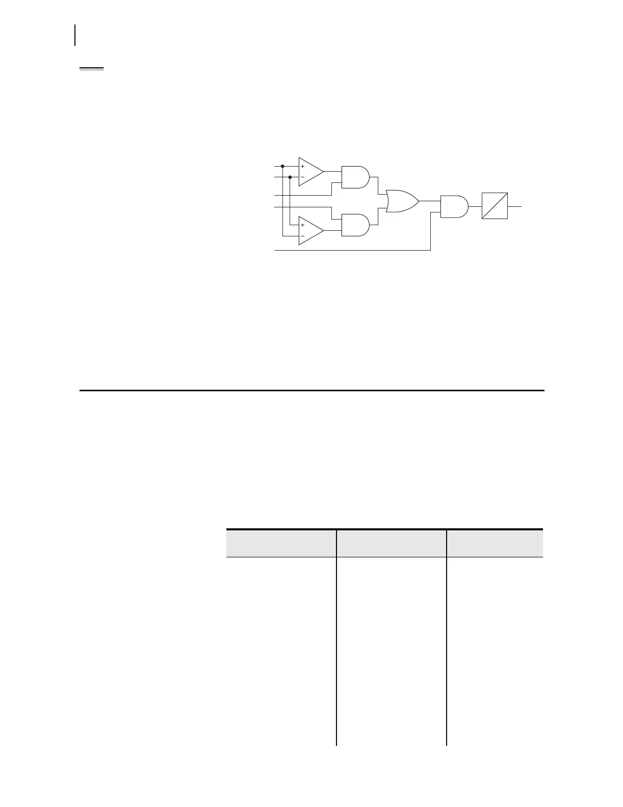
The SEL-751A provides six trip over- or underfrequency elements with
independent level and time-delay settings. When an element level setting is
less than the nominal frequency setting, the element operates as an
underfrequency element. When the level setting is greater than the nominal
frequency setting, the element operates as an overfrequency element.
Figure 4.27 shows the logic diagram for the frequency elements.
Figure 4.27 Over- and Underfrequency Element Logic
Rate-of-Change of Frequency Protection
Frequency changes occur in power systems when there is an unbalance
between load and active power generated. Typically, generator control action
adjusts the generated active power and restores the frequency to nominal
value. Failure of such control action may lead to system instability unless
remedial action, such as load shedding, is taken. You can use the rate of
change of frequency element to detect and initiate a remedial action. The
SEL-751A provides four rate-of-change of frequency elements. Tabl e 4.23
shows settings available for the elements.
freq
81DnTP
81DnT
81DnTP < FNOM
FREQTRK
81DnTD
0
Frequency Elements 1–6
Measured Frequency
Frequency Pickup Setting
Nominal Frequency Setting
Over- and Underfrequency Element Pickup Time Delay
Definite-Time Delayed Over- and Underfrequency Element Relay Word Bit
Relay Is Tracking Frequency
n =
freq =
81DnTP =
FNOM =
81DnTD =
81DnT =
FREQTRK =
81DnTP ≥ FNOM
Table 4.23 Rate-of-Change-of-Frequency Settings (Sheet 1 of 2)
Setting Prompt Setting Range
Setting Name :=
Factory D efault
ENABLE 81R OFF, 1–4 E81R := OFF
81R VOLTAGE SUP OFF, 0.1–1.3*Vnm
a
81RVSUP := 0.1*Vnm
81R CURRENT SUP OFF, 0.1–2.0*
I
NOM
b
81RISUP := OFF
81R1 TRIP LEVEL OFF, 0.10–15.00 81R1TP := OFF
81R1 TREND INC, DEC, ABS 81R1TRND := ABS
81R1 TRIP DELAY 0.10–60.00 sec 81R1TD := 1.00
81R1 DO DELAY 0.00–60.00 sec 81R1DO := 0.00
81R2 TRIP LEVEL OFF, 0.10–15.00 81R2TP := OFF
81R2 TREND INC, DEC, ABS 81R2TRND := ABS
81R2 TRIP DELAY 0.10–60.00 sec 81R2TD := 1.00