2.11
Date Code 20100129 Instruction Manual SEL-751A Relay
Installation
I/O Configuration
Step 13. Attach the terminal marking label (provided with the card) to
the rear cover so that the INTERFACE CARD EXPANSION SLOT is
covered.
Step 14. Reconnect all connection plugs, and add any additional wiring/
connectors required by the new option card.
Analog Input Card
Voltage/Current
Jumper Selection
Figure 2.3 shows the circuit board of an analog I/O board. Jumper x (x = 1–8)
determines the nature of each channel. For a current channel, insert Jumper x
in position 1–2; for a voltage channel, insert Jumper x in position 2–3.
Figure 2.3 Circuit Board of Analog I/O Board, Showing Jumper Selection
Analog Output (AO)
Configuration Jumper
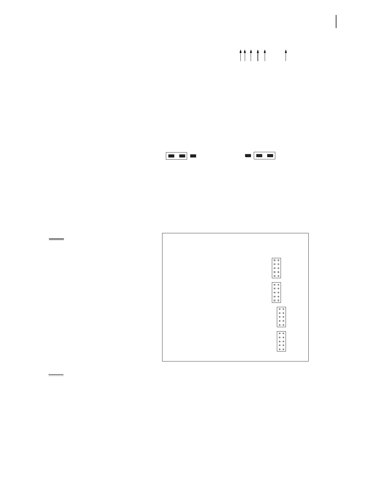
Figure 2.4 shows the locations of JMP1 through JMP4 on an Analog Output
board. You can select each of the four analog output channels as either a
current analog output or a voltage analog output.
Figure 2.4 JMP1 Through JMP4 Locations on 4 AI/4 AO Board
NOTE:
There is no jumper between
pins 5 and 6 for a voltage analog
output selection.
You need to insert three jumpers for a current analog output selection and two
jumpers for a voltage analog output selection. For a current analog output
selection, insert a jumper between pins 1 and 2, pins 5 and 6, and pins 9 and
10. For a voltage analog output selection, insert a jumper between pins 3 and
4, and pins 7 and 8. Figure 2.5 shows JMP4 selected as a current analog
output. The current analog output selection is the default setting for JMP1
through JMP4. Figure 2.6 shows JMP1 selected as a voltage analog output.
PART NUM = 751A01B5X1X7X86020X
JMPX
21 3
JMPX
213
Position 2 – 3 = V (voltage) mode
Where "JMPX" is the
um
er for AI channel "X"
Position 1 – 2 = I (current) mode
NOTE: Analog inputs cannot provide
loop power. Each analog output is self
powered and has an isolated power
supply.
9
7
5
3
1
10
8
6
4
2
JMP1
9
7
5
3
1
10
8
6
4
2
JMP2
9
7
5
3
1
10
8
6
4
2
JMP3
9
7
5
3
1
10
8
6
4
2
JMP4