5.18
SEL-751A Relay Instruction Manual Date Code 20100129
Metering and Monitoring
Breaker Monitor
Breaker Maintenance Curve Details
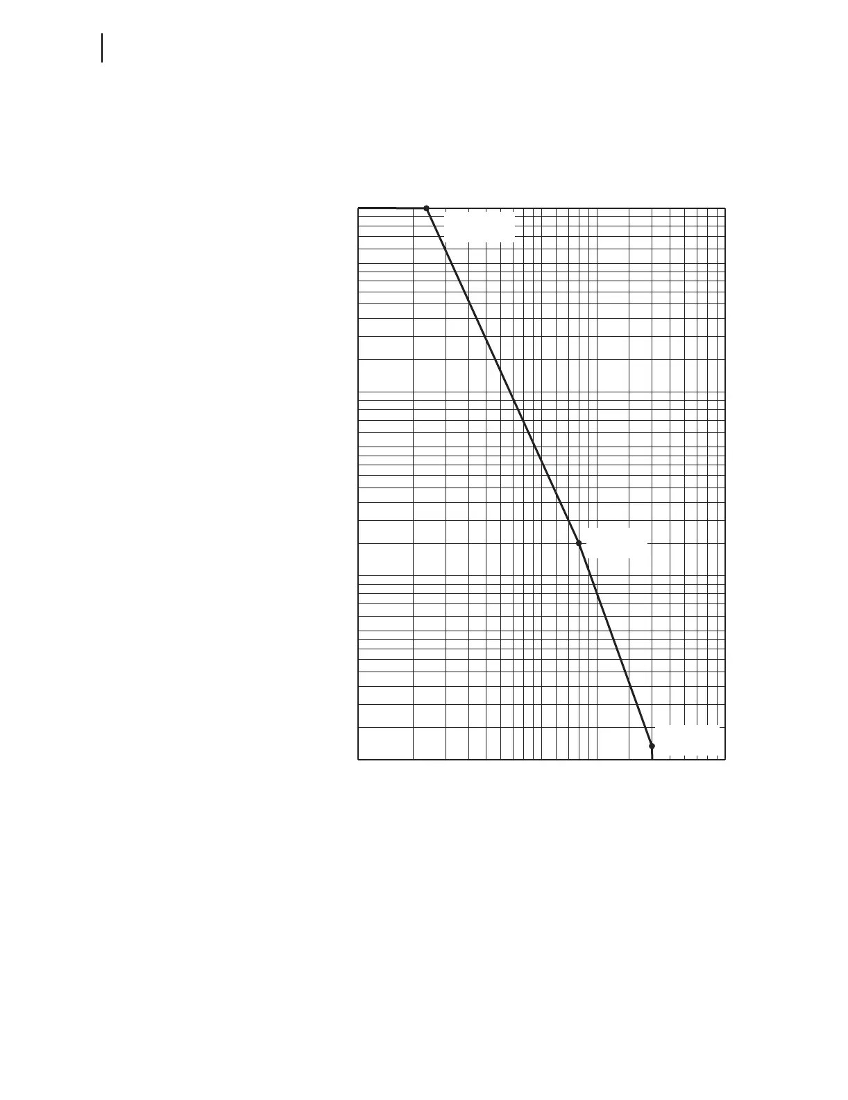
In Figure 5.18, note that set points KASP1, COSP1 and KASP3, COSP3 are
set with breaker maintenance information from the two extremes in Table 5.9
and Figure 5.17.
Figure 5.18 SEL-751A Breaker Maintenance Curve for a 25 kV Circuit
Breaker
In this example, set point KASP2, COSP2 happens to be from an in-between
breaker maintenance point in the breaker maintenance information in
Table 5.9 and Figure 5.17, but it does not have to be. Set point KASP2,
COSP2 should be set to provide the best “curve-fit” with the plotted breaker
maintenance points in Figure 5.17.
Each phase (A, B, and C) has its own breaker maintenance curve (like that in
Figure 5.18), because the separate circuit breaker interrupting contacts for
phases A, B, and C do not necessarily interrupt the same magnitude current
(depending on fault type and loading).
10,000
100%
1000
2
3
4
5
6
7
8
9
100
2
3
4
5
6
7
8
9
10
2
3
4
5
6
7
8
9
123456789
50
40
30
20
10
.5
Number of Close/Open Operations
kA Interrupted per Operation
KASP1 = 1.2
COSP1 = 10000
KASP2 = 8.0
COSP2 = 150
KASP3 = 20.0
COSP3 = 12