4.31
Date Code 20100129 Instruction Manual SEL-751A Relay
Protection and Logic Functions
Voltage-Based Protection
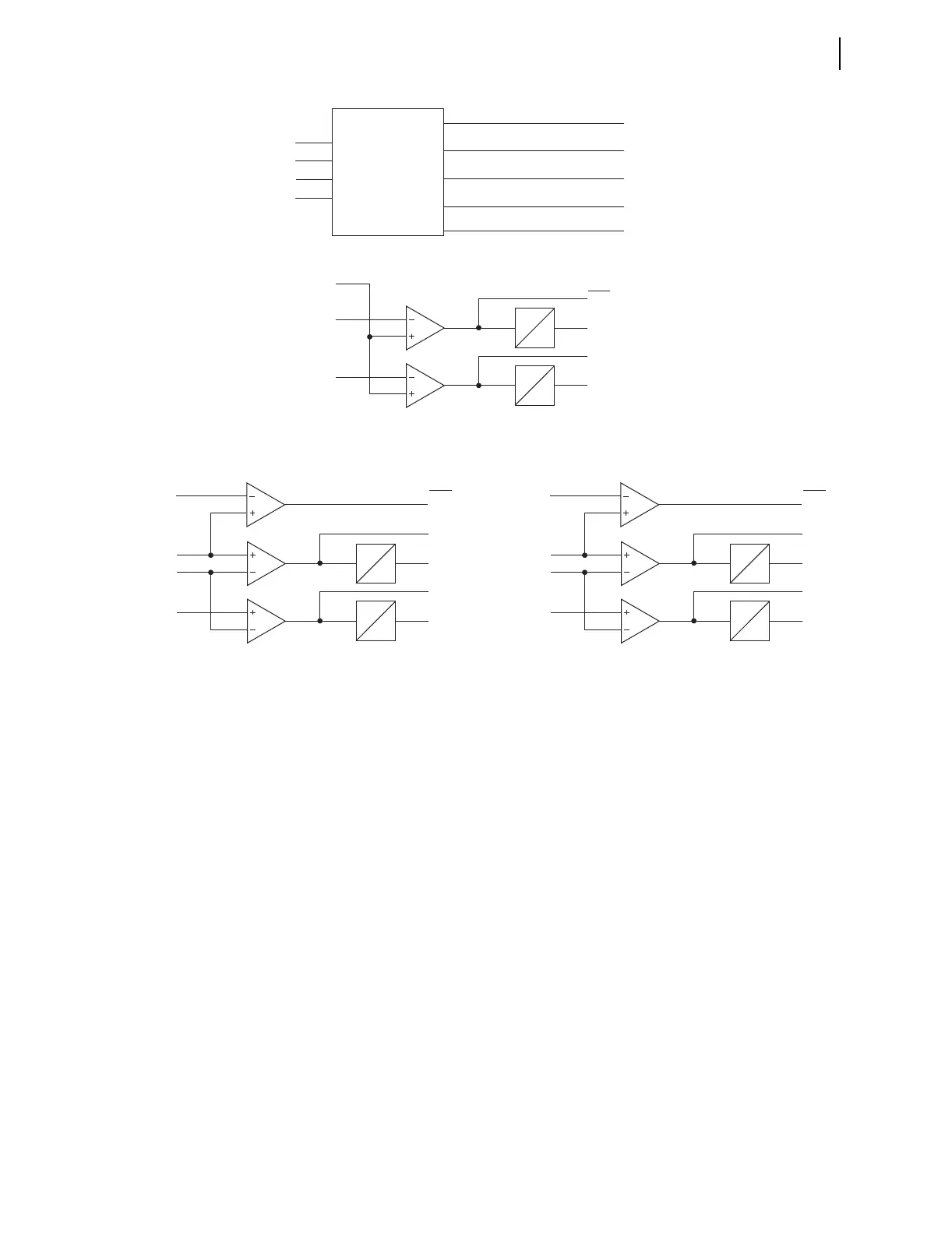
Figure 4.18 Undervoltage Element Logic
Synch Voltage Elements
27S1P
|VS|
27S1D
0
27S1T
27S2P
27S2D
0
27S2T
Relay
Word
Bits
27S2
27S1
27S1P, 27S2P, 27P1P, 27P2P =
Vnm =
Settings
Effective Nominal Voltage
When DELTA_Y := WYE
27P1P • Vnm
|VP| max
27P1D
0
27P1T
27P2P • Vnm
27P2D
0
27P2T
Relay
Word
Bits
27P1
27P2
3P27
|VP| min
When DELTA_Y := DELTA
27P1P • Vnm
|VPP| max
27P1D
0
27P1T
27P2P • Vnm
27P2D
0
27P2T
Relay
Word
Bits
3P27
|VPP| min
27P1
27P2
VAB or VA
VBC or VB
VCA or VC
Voltage
Magnitude
Calculation
|VS|
|VP| min
(Minimum Phase Voltage Magnitude)
VS
(Maximum Phase Voltage Magnitude)
|VP| max
(Maximum Phase-to-Phase Voltage Magnitude)
|VPP| max
(Minimum Phase-to-Phase Voltage Magnitude)
|VPP| min