2.23
Date Code 20100129 Instruction Manual SEL-751A Relay
Installation
AC/DC Control Connection Diagrams
Station DC Battery
Monitor
Use the station dc battery monitor (one of the options available with the
Voltage Card options) in the SEL-751A to alarm for undervoltage and
overvoltage dc battery conditions and to view how station dc battery voltage
fluctuates during tripping, closing, and other dc control functions. The
monitor measures station dc battery voltage applied to the rear-panel terminals
E07 (VBAT+) and E08 (VBAT-) of the SELECT 5AVI voltage card in slot E.
Refer to Section 5: Metering and Monitoring for details on the station dc
battery monitor function and settings.
AC/DC Connections
and Applications
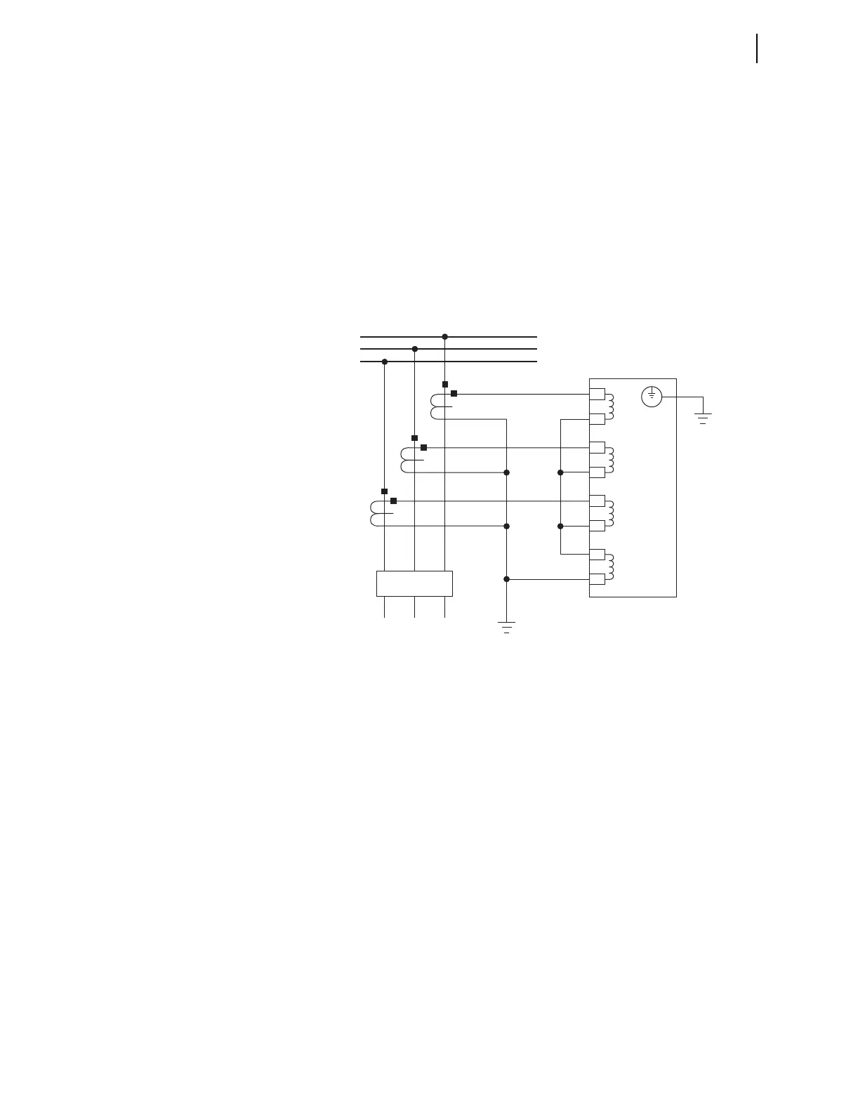
Figure 2.19 shows typical phase and neutral current connections for a feeder
application. Figure 2.20 through Figure 2.24 show ac/dc connection diagrams
for various applications, however, wye-connected PTs are shown. See
Figure 2.17 and Figure 2.18 for other voltage connections.
Figure 2.19 Typical Current Connections
SEL-751A
The current transformers and the SEL-751A
chassis must be grounded in the relay cabinet.
A
B
C
IN
IC
IB
IA
Z08
Z07
Z06
Z05
Z04
Z03
Z02
Z01
52
FEEDER
BUS