4.3
Date Code 20100129 Instruction Manual SEL-751A Relay
Protection and Logic Functions
Application Data
Application Data
It is faster and easier for you to calculate settings for the SEL-751A if you
collect the following information before you begin:
➤ Highest expected load current
➤ Current transformer primary and secondary ratings and
connections
➤ System phase rotation and nominal frequency
➤ Voltage transformer ratios and connections, if used
➤ Type and location of resistance temperature devices (RTDs), if
used
➤ Expected fault current magnitudes for ground and three-phase
faults
Group Settings (SET Command)
ID Settings
All models of the SEL-751A have the identifier settings described in
Table 4.1.
The SEL-751A prints the Relay and Terminal Identifier strings at the top of
the responses to serial port commands to identify messages from individual
relays.
Enter up to 16 characters, including letters A–Z (not case sensitive), numbers
0–9, periods (.), dashes (-), and spaces. Suggested identifiers include the
location or number of the protected feeder.
Configuration
Settings
The CT ratio settings configure the relay to accurately scale measured values
and report the primary quantities. Calculate the phase and neutral CT ratios by
dividing the primary rating by the secondary rating.
EXAMPLE 4.1 Phase CT Ratio Setting Calculation
Consider an application where the phase CT rating is 100:5 A.
Set CTR := 100/5 := 20.
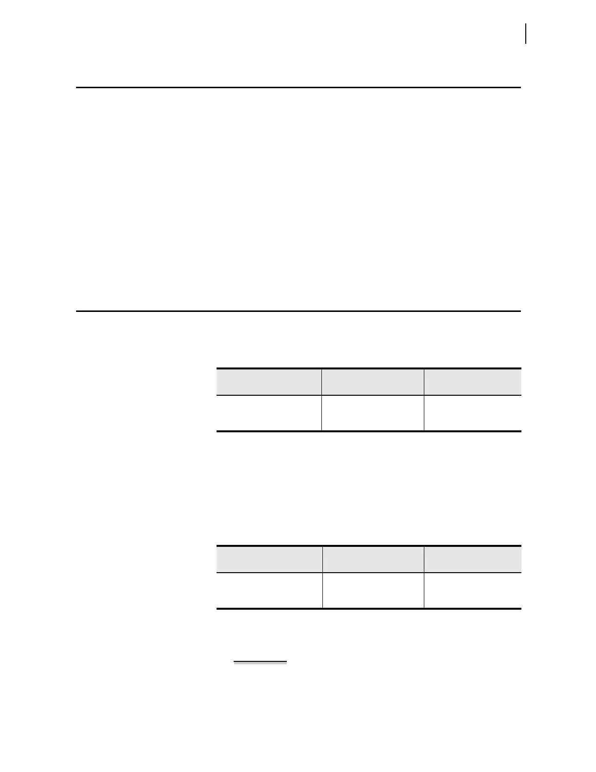
Table 4.1 Identifier Settings
Setting Prompt Setting Range
Setting Name :=
Factor y Defau lt
UNIT ID LINE 1 16 Characters RID := SEL-751A
UNIT ID LINE 2 16 Characters TID := FEEDER RELAY
Table 4.2 CT Configuration Settings
Setting Prompt Setting Range
Setting Name :=
Facto ry Default
PHASE CT RATIO 1–5000 CTR := 120
NEUTRAL CT RATIO 1–5000 CTRN := 120