5.25
Date Code 20100129 Instruction Manual SEL-751A Relay
Metering and Monitoring
Breaker Monitor
Determination of
Relay Initiated Trips
and Externally
Initiated Trips
See Section 7: Communications. Note in the BRE command response that the
accumulated number of trips and accumulated interrupted current are
separated into two groups of data: that generated by relay initiated trips (Rly
Trips) and that generated by externally initiated trips (Ext Trips). The
categorization of this data is determined by the status of the TRIP Relay Word
bit when the SEL
OGIC control equation breaker monitor initiation setting
BKMON operates.
Refer to Figure 5.19 and accompanying explanation. If BKMON newly
asserts (logical 0 to logical 1 transition), the relay reads in the current values
(Phases A, B, and C). Now the decision has to be made: where is this current
and trip count information accumulated? Under relay initiated trips or
externally initiated trips?
To make this determination, the status of the TRIP Relay Word bit is checked
at the instant BKMON newly asserts (TRIP is the logic output of Figure 4.29
on page U.4.51). If TRIP is asserted (TRIP = logical 1), the current and trip
count information is accumulated under relay initiated trips (Rly Trips). If
TRIP is deasserted (TRIP = logical 0), the current and trip count information
is accumulated under externally initiated trips (Ext Trips).
Regardless of whether the current and trip count information is accumulated
under relay initiated trips or externally initiated trips, this same information is
routed to the breaker maintenance curve for continued breaker wear
integration (see Figure 5.19–Figure 5.23).
Relay initiated trips (Rly Trips) are also referred to as internally initiated
trips (Int Trips) in the course of this manual; the terms are interchangeable.
EXAMPLE 5.2 Factory Default Setting Example
As discussed previously, the SEL
OGIC control equation breaker
monitor initiation factory default setting is:
BKMON = TRIP
Thus, any new assertion of BKMON will be deemed a relay trip, and
the current and trip count information is accumulated under relay
initiated trips (Rly Trips).
EXAMPLE 5.3 Additional Example
Refer to Figure 5.24. Output contact OUT103 is set to provide tripping:
OUT103 = TRIP
Note that optoisolated input INxxx monitors the trip bus. If the trip bus
is energized by output contact OUT101, an external control switch, or
some other external trip, then INxxx is asserted.
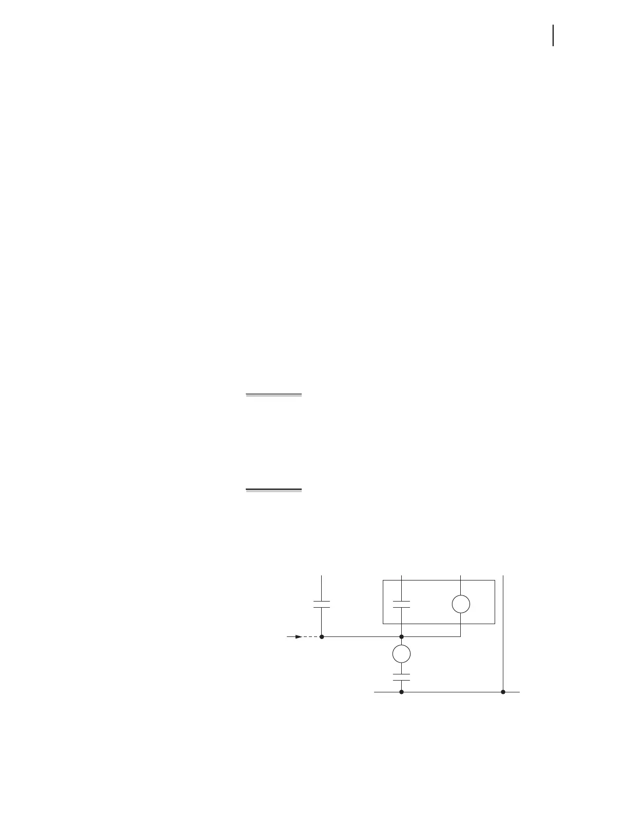
Figure 5.24 Input INxxx Connected to Trip Bus for Breaker Monitor
Initiation
TC
CS/T
(Control
Switch Trip)
Other
External
Trips
OUT101
= TRIP
TRIP
COIL
52A
INxxx
Trip Bus
SEL-751A
(—)