8.12
SEL-751A Relay Instruction Manual Date Code 20100129
Front-Panel Operations
Operation and Target LEDs
Breaker Menu
Select the Breaker menu item on the MAIN menu as shown in Figure 8.23 to
access
Breaker Monitor data or Reset the data. See Breaker Monitor on
page 5.15, in Section 5: Metering and Monitoring for a detailed description.
Figure 8.23 MAIN Menu and Breaker Submenu
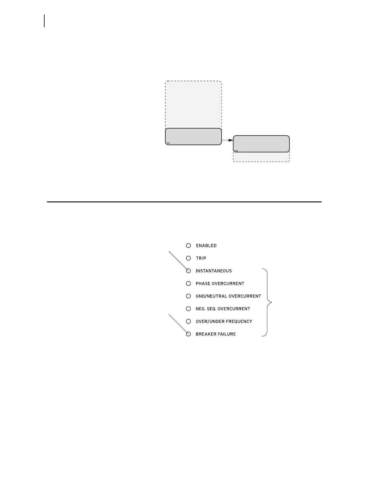
Operation and Target LEDs
Programmable LEDs
The SEL-751A provides quick confirmation of relay conditions via operation
and target LEDs. Figure 8.24 shows this region with factory default text on the
front-panel configurable labels. See Target LED Settings on page 4.120 for the
SEL
OGIC control equations.
Figure 8.24 Factory Default Front-Panel LEDs
You can reprogram all of these indicators except the ENABLED and TRIP LEDs
to reflect operating conditions other than the factory-default programming
described in this subsection.
Settings T0n_LED are SEL
OGIC control equations that, when asserted during
a relay trip event, illuminate the corresponding LED. Parameter n is a number
from 1 through 6 that indicates each LED. The target LEDs can be set to latch
by the user. The setting T0nLEDL is set to Y to accomplish this. This setting
is set to N to disable the latch. After setting the target LEDs, issue the TAR R
command to reset the target LEDs. For a concise listing of the default
programming on the front-panel LEDs, see Table 4.66.
(Breaker Selected)
BREAKER
Display
Reset
MAIN
Meter
Events
Targets
Control
Set/Show
Status
Breaker
T01_LED
Factory Default Label
T06_LED