4.82
SEL-751A Relay Instruction Manual Date Code 20100129
Protection and Logic Functions
Logic Settings (SET L Command)
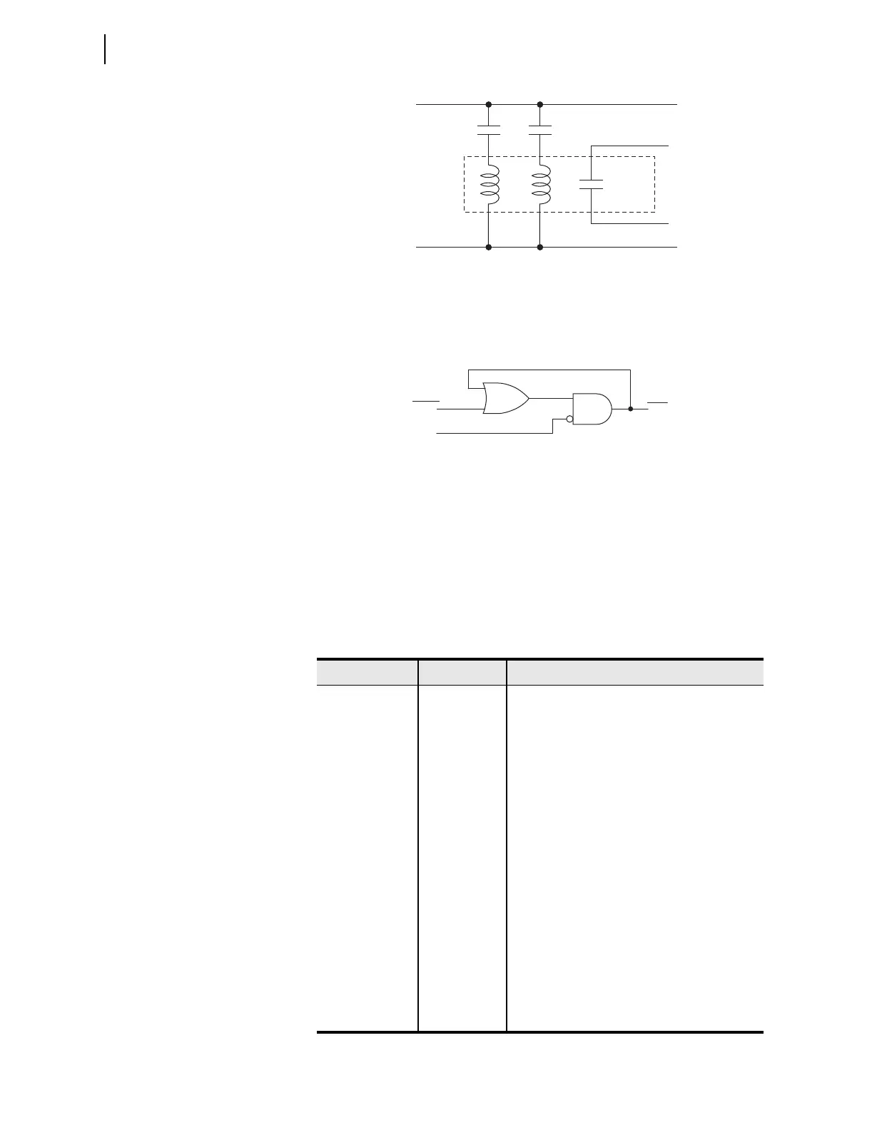
Figure 4.43 Schematic Diagram of a Traditional Latching Device
Thirty-two latch control switches in the SEL-751A provide latching device
functionality. Figure 4.44 shows the logic diagram of a latch switch. The
output of the latch control switch is a Relay Word bit LTn (n = 01–32), called
a latch bit.
Figure 4.44 Logic Diagram of a Latch Switch
If setting SETn asserts to logical 1, latch bit LTn asserts to logical 1. If setting
RSTn asserts to logical 1, latch bit LTn deasserts to logical 0. If both settings
SETn and RSTn assert to logical 1, setting RSTn has priority and latch bit LTn
deasserts to logical 0. You can use these latch bits in SEL
OGIC control
equations to create custom logic for your application.
The SEL-751A includes 32 latches. Table 4.32 shows the SET and RESET
default settings for Latch 1 through Latch 4. The remaining latches are all set
to NA.
Table 4.32 Latch Bits Equation Settings
Settings Prompt Setting Range Setting Name := Factory Default
SET01 SELOGIC SET01 := NA
RST01 SELOGIC RST01 := NA
SET02 SEL
OGIC SET02 := R_TRIG SV02T AND NOT LT02
RST02 SEL
OGIC RST02 := R_TRIG SV02T AND LT02
SET03 SELOGIC SET03 := PB03_PUL AND LT02 AND NOT 52A
RST03 SEL
OGIC RST03 := (PB03_PUL OR PB04_PUL OR
SV03T) AND LT03
SET04 SELOGIC SET04 := PB04_PUL AND 52A
RST04 SEL
OGIC RST04 := (PB03_PUL OR PB04_PUL OR
SV04T) AND LT04
•
•
•
•
•
•
•
•
•
SET32 SEL
OGIC SET32 := NA
RST32 SEL
OGIC RST32 := NA
Set
Input
Reset
Input
Output
Contact
Traditional
Latching
Relay
(+)
(–)
LTn
SETn
RSTn
(Set)
(Reset)
(n = 01 through 32)
Relay
Word
Bits
SELOGIC
Setting