2.15
Date Code 20100129 Instruction Manual SEL-751A Relay
Installation
Rear-Panel Connections
Rear-Panel Connections
Rear-Panel and
Side-Panel Diagrams
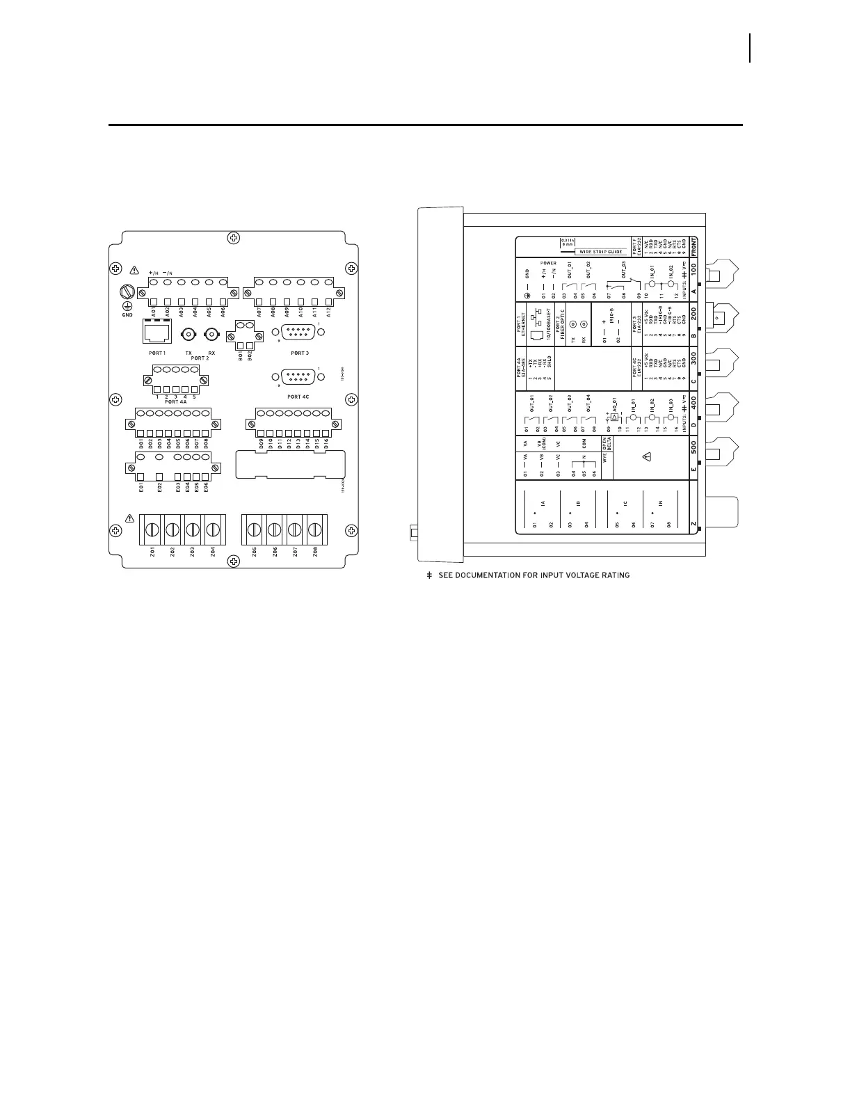
The physical layout of the connectors on the rear-panel and side-panel
diagrams of three sample configurations of the SEL-751A are shown in
Figure 2.9, Figure 2.10, and Figure 2.11.
Figure 2.9 Fiber-Optic Serial, Ethernet, EIA-232 Communication, 3 DI/4 DO/1 AO, and 3 AVI Voltage Option
710_IM_0133_IRIG-BRP-B_i3970c.eps
i3970c
(A) Rear-Panel Layout
(B) Side-Panel Input and Output Designations