2.2
SEL-751A Relay Instruction Manual Date Code 20100129
Installation
I/O Configuration
Relay Mounting
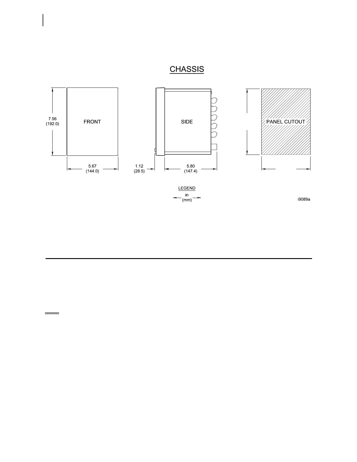
To flush mount the SEL-751A in a panel, cut a rectangular hole with the
dimensions shown in Figure 2.1. Use the supplied front-panel gasket for
protection against dust and water ingress into the panel (IP65).
Figure 2.1 Relay Panel-Mount Dimensions
Refer to Section 1: Introduction and Specifications, Models, Options, and
Accessories for information on mounting accessories.
I/O Configuration
Your SEL-751A offers flexibility in tailoring I/O to your specific application.
In total, the SEL-751A has six rear-panel slots, labeled as Slots A, B, C, D, E,
and Z. Slots A, B, and Z are base unit slots, each associated with a specific
function. Optional digital/analog I/O, communications, RTD, and voltage
cards are available for the SEL-751A. Figure 2.2 shows the slot allocations for
the cards.
Because installations differ substantially, the SEL-751A offers a variety of
card configurations to provide options for the many diverse applications.
Choose the combination of option cards most suited for your application from
the following selection.
7.36
(187.0)
5.47
(139.0)
NOTE: When either a current or
voltage signal is available, the
SEL-751A tracks the frequency and
samples 16 times a cycle at the
measured frequency. If neither signal
is available, the
relay samples at a
fixed rate of 16 times nominal
frequency.