2.30
SEL-751A Relay Instruction Manual Date Code 20100129
Installation
Arc-Flash Protection: System Installation
Figure 2.26 Jacketed-Fiber installation Example
Fiber-bending radius must be kept above 50 mm (2 in) Care should be
exercised when crossing from a moving part (such as control cabinet door) to
a stationary switchgear enclosure. Use standard wiring practices with bundled
fibers and well-defined strain relief points. Additional attention is required to
prevent moving parts, such as a breaker truck assembly, from inadvertently
damaging the arc-flash sensor fibers. Although easily detected by the sensor
diagnostics, such problems can be eliminated through careful installation
planning. Once routed, fiber sensors are connected to the SEL-751A relay as
shown in Figure 2.27.
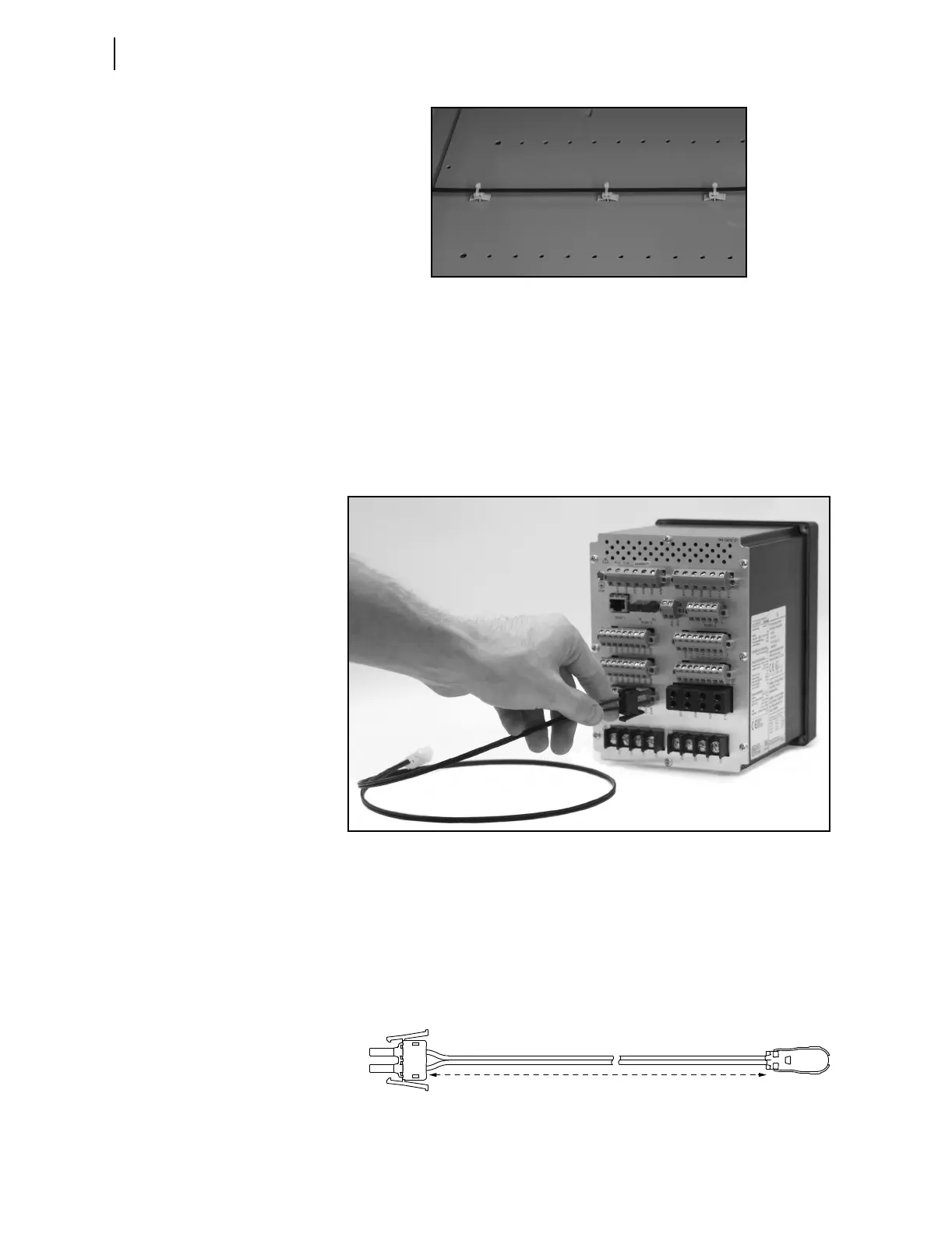
Figure 2.27 Connecting Sensor Fibers to the Relay
Point-Sensor
Installation
The point-sensor is optimized for monitoring confined switchgear spaces
where the distance between sensors and the potential sources of arc (energized
parts) can be kept below 2 m. Such spaces typically include breaker
compartments, outgoing and incoming cable compartments, and potential
transformer (PT) compartments. Figure 2.28 shows a schematic diagram of
the point-sensor assembly.
Figure 2.28 Point-Sensor Assembly
Dual V-pin
Latch
V-pin
Terminators
Jacketed Fiber Zipcord Duplex
01-35 Meters
Sensor