4.33
Date Code 20100129 Instruction Manual SEL-751A Relay
Protection and Logic Functions
Voltage-Based Protection
Synchronism-Check
Elements
Figure 2.20, and Figure 2.21 show examples where synchronism check can be
applied. Synchronism-check voltage input VS is connected to one side of the
circuit breaker, on any desired phase. The other synchronizing phase (VA, VB,
or VC voltage inputs) on the other side of the circuit breaker is setting selected.
The two synchronism-check elements use the same voltage window (to assure
healthy voltage), frequency window (FNOM +/- 5 Hz), and slip frequency
settings (see Figure 4.20 and Figure 4.21). They have separate angle settings.
If the voltages are static (voltages not slipping with respect to one another) or
setting TCLOSD = OFF, the two synchronism-check elements operate as
shown in the top of Figure 4.21. The angle settings are checked for
synchronism-check closing.
If the voltages are not static (voltages slipping with respect to one another),
the two synchronism-check elements operate as shown in the bottom of
Figure 4.21. The angle difference is compensated by breaker close time, and
the breaker is ideally closed at a zero-degree phase angle difference, to
minimize system shock.
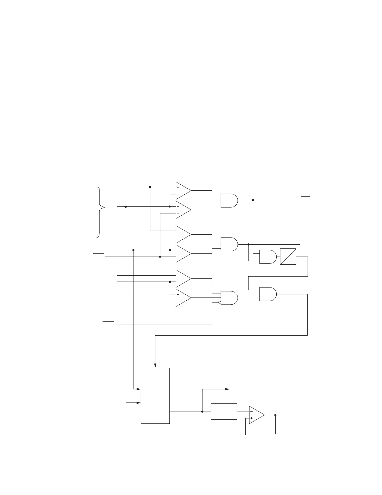
Figure 4.20 Synchronism-Check Voltage Window and Slip Frequency Elements
59VP
59VS
SF
to Figure 4.21
Relay
Word
Bits
25VLO
Setting
25SF
Setting
BSYNCH
SEL
OGIC
Setting
25VHI
VP
VS
Setting
Block Synchronism Check
VP Within
"Healthy Voltage" Window
VS Within
"Healthy Voltage" Window
Slip
Frequency
Calculator
Enable
2 CYC
to Angle Difference
Calculator—to Figure 4.21
Slip Frequency
Maximum Slip Frequency
Absolute Value
Slip
Frequency Element
SF
(FNOM + 5) Hz
FREQ
(FNOM —5) Hz
VP = 25RCF*VPH
where VPH = VA, VB, VC,
VAB, VBC, or VCA
depending on
the SYNCPH setting.
High Threshold
High Threshold
High Threshold
Low Threshold
Low Threshold
Low Threshold
0