4.83
Date Code 20100129 Instruction Manual SEL-751A Relay
Protection and Logic Functions
Logic Settings (SET L Command)
Latch Bits:
Nonvolatile State
Power Loss
The states of the latch bits (LT01–LT32) are retained if power to the device is
lost and then restored. If a latch bit is asserted (e.g., LT02 := logical 1) when
power is lost, it is asserted (LT02 := logical 1) when power is restored. If a
latch bit is deasserted (e.g., LT03 := logical 0) when power is lost, it is
deasserted (LT03 := logical 0) when power is restored.
Settings Change
If individual settings are changed, the states of the latch bits (Relay Word bits
LT01 through LT32) are retained, as in the preceding Power Loss on page 4.83
explanation. If the individual settings change causes a change in SEL
OGIC
control equation settings SETn or RSTn (n = 1 through 32), the retained states
of the latch bits can be changed, subject to the newly enabled settings SETn or
RSTn.
Make Latch Control Switch Settings With Care
The latch bit states are stored in nonvolatile memory so they can be retained
during power loss or settings change. The nonvolatile memory is rated for a
finite number of writes for all cumulative latch bit state changes. Exceeding
the limit can result in a flash self-test failure. An average of 70 cumulative
latch bit state changes per day can be made for a 25-year device service life.
Settings SETn and RSTn cannot result in continuous cyclical operation of
latch bit LTn. Use timers to qualify conditions set in settings SETn and RSTn.
If you use any optoisolated inputs in settings SETn and RSTn, the inputs each
have a separate debounce timer that can help in providing the necessary time
qualification.
SELOGIC Control
Equation Variables/
Timers
Enable the number of SELOGIC control equations necessary for your
application. Only the enabled SEL
OGIC control equations appear for settings.
Each SEL
OGIC control equation variable/timer has a SELOGIC control
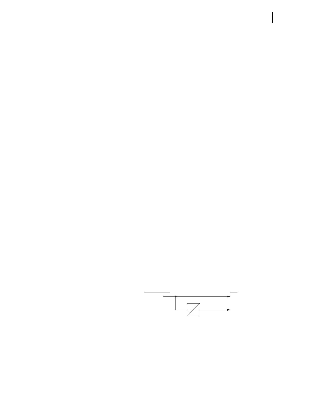
equation setting input and variable/timer outputs as shown in Figure 4.45.
Timers SV01T through SV32T in Figure 4.45 have a setting range of 0.00–
3000.00 seconds. This timer setting range applies to both pickup and dropout
times (SVnPU and SVnDO, n = 1 through 32).
Figure 4.45 SELOGIC Control Equation Variable/Timers SV01/SV01T—SV32T
You can enter up to 15 elements per SELOGIC equation, including a total of 14
elements in parentheses (see Table 4.33 for more information).
SVn
SVn
SVnT
SEL
OGIC Variable/
Timer Input Settings
Relay
Word
Bits
SVnPU
SVnDO