4.51
Date Code 20100129 Instruction Manual SEL-751A Relay
Protection and Logic Functions
Trip/Close Logic
NOTE: The factory default
assignment of the Relay Word bit TRIP
is the output OUT103. See Tab le 4.38
for the output contacts settings.
The SEL-751A tripping logic is designed to trip the circuit breakers. The relay
logic lets you define the conditions that cause a trip, the conditions that
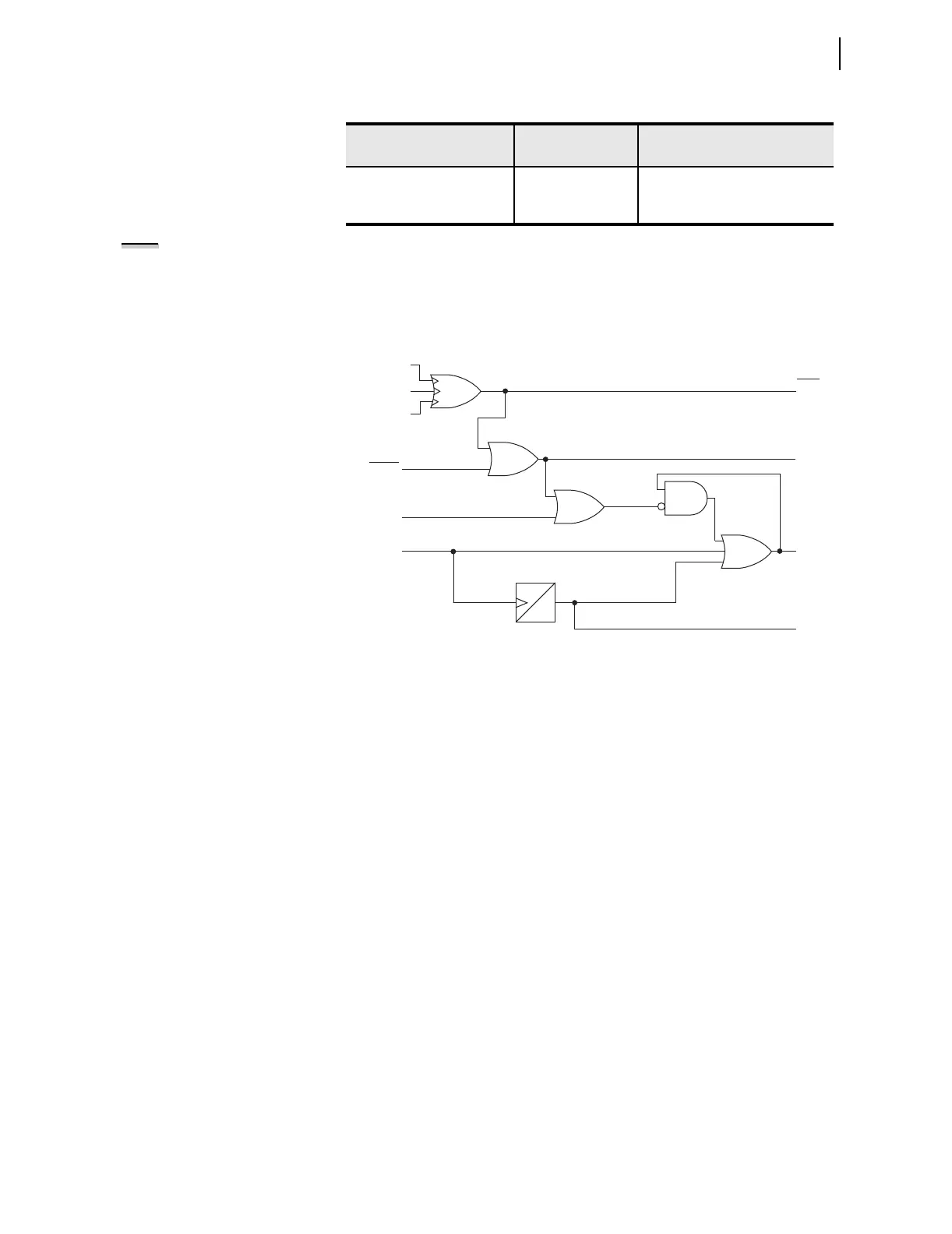
unlatch the trip, and the performance of the relay output contact. Figure 4.29
illustrates the tripping logic.
Figure 4.29 Trip Logic
The trip logic settings, including the SELOGIC control equations, are described
below.
TDURD Minimum Trip Time
This timer establishes the minimum time duration for which the TRIP Relay
Word bit asserts. This is a rising-edge initiated timer.
Trips initiated by the TR Relay Word bit (includes OPEN command from
front-panel and serial ports) are maintained for at least the duration of the
minimum trip duration time (TDURD) setting.
TR Trip Conditions SELOGIC Control Equation
The SEL-751A Trip Logic offers two ways to trip the breaker:
➤ Conditions mapped to TR
➤ Front panel or serial port (including Modbus and DeviceNet)
OPEN command
Either of the two conditions will trigger an event report. The relay controls the
tripping output contact(s) when the Relay Word bit TRIP appears in an output
contact SEL
OGIC control equation. Default relay settings have output OUT103
set to TRIP and fail-safe setting OUT103FS at N (see Fail-Safe/Nonfail-Safe
Tripping on page 2.20).
CLOSE EQUATION SV
CL := SV03T AND LT02 OR CC
UNLATCH CLOSE SV
ULCL := 0
Table 4.25 Trip/Close Logic Settings (Sheet 2 of 2)
Setting Prompt Setting Range
Setting Name := Factory
Default
0
TDURD
Serial Port
Command TAR R
TARGET RESET
Pushbutton
TRGTR
Reset
TRIP LED
TRIP
Trigger
Events
Unlatch Trip
Other Trips
Comm.
Target Reset
RSTTRGT
ULTRIP
TR
Relay
Word
Bits
SELOGIC
Settings