1.15
Date Code 20100129 Instruction Manual SEL-751A Relay
Introduction and Specifications
Applications
➤ Rack-Mounting Kits
➢ For one relay
➢ For two relays
➢ For one relay and a test switch
➤ Wall-Mounting Kits
➤ Bezels for Retrofit
➤ Replacement Rear Connector Kit
For all SEL-751A mounting accessories for competitor products, including
adapter plates, visit http://www2.selinc.com/mounting_selector/.
Applications
Section 2: Installation includes ac and dc connection diagrams for various
applications. The following is a list of possible application scenarios:
➤ Distribution feeder protection (feeder protection with core-
balance CT)
➤ Delta-wye transformer overcurrent protection
➤ Wye-delta-wye transformer overcurrent protection
➤ With or without external RTD module
➤ With Arc-Flash Protection
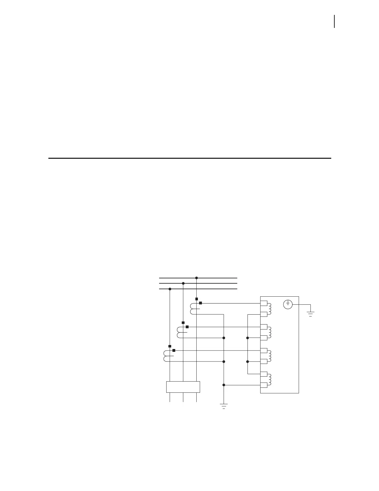
Figure 1.1 shows typical current connections. Refer to Section 2: Installation
for additional applications and the related connection diagrams.
Figure 1.1 Typical Current Connections
SEL-751A
The current transformers and the SEL-751A
chassis must be grounded in the relay cabinet.
A
B
C
IN
IC
IB
IA
Z08
Z07
Z06
Z05
Z04
Z03
Z02
Z01
52
FEEDER
BUS