5.13
Date Code 20100129 Instruction Manual SEL-751A Relay
Metering and Monitoring
Station DC Battery Monitor
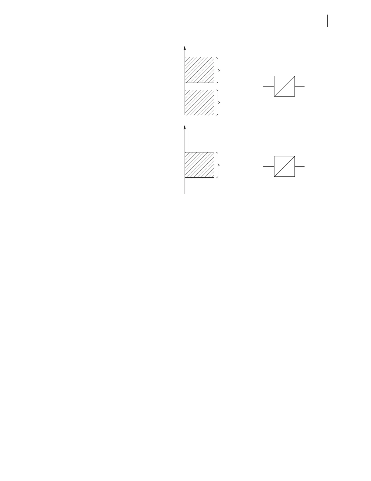
Figure 5.16 Create DC Voltage Elements With SELOGIC Control Equations
DCLO < DCHI (Top of Figure 5.16)
Output contact OUTxxx asserts when:
V
dc
≤ DCLOP or V
dc
≥ DCHIP
Pickup settings DCLOP and DCHIP are set such that output contact OUTxxx
asserts when dc battery voltage goes below or above allowable limits.
If the relay loses power entirely (V
dc
= 0 V)
V
dc
= < DCLOP
then output contact OUTxxx should logically assert (according to top of
Figure 5.16), but cannot because of the total loss of power (all output contacts
deassert on total loss of power). Thus, the resultant dc voltage element at the
bottom of Figure 5.16 would probably be a better choice—see following
discussion.
DCLO > DCHI (Bottom of Figure 5.16)
Output contact OUTxxx asserts when:
DCHIP ≤ V
dc
≤ DCLOP
Pickup settings DCLOP and DCHIP are set such that output contact OUTxxx
asserts when dc battery voltage stays between allowable limits.
If the relay loses power entirely (V
dc
= 0 V)
V
dc
= < DCHIP
then output contact OUTxxx should logically deassert (according to bottom of
Figure 5.16), and this is surely what happens for a total loss of power (all
output contacts deassert on total loss of power).
SVnPU
SVnDO
SVn SVnT
SVnT
DCHI
SVn = DCLO + DCHI
OUTxxx = SVnT
DCLO
DCLOP
DCHIP
DCLOP < DCHIP
V
dc
SVnPU
SVnDO
SVn
DCLO * DCHI
SVn = DCLO * DCHI
OUTxxx = SVnT
DCLOP
DCHIP
DCLOP > DCHIP
V
dc