The statistics information can be individually set and reset via the device control. It is also possible to reset all
values via the binary input signal >Reset switch statist..
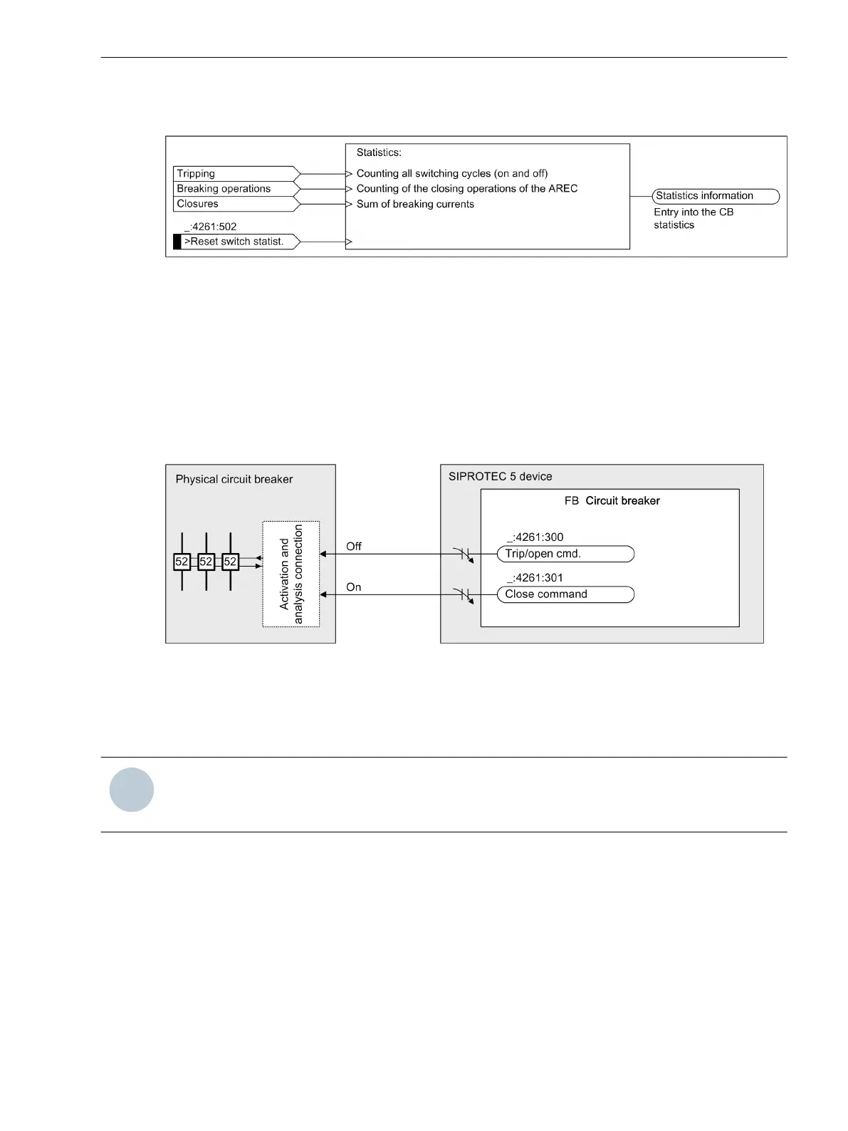
[lo_statistics information circuit-breaker, 2, en_US]
Figure 5-81 Statistics Information About the Circuit Breaker
Application and Setting Notes
Routings for Activation of the Circuit Breaker
Figure 5-82 shows the necessary routings:
•
The device can execute 3-pole tripping (via the protection device).
•
The device can execute 3-pole opening (via the control).
•
The device can execute 3-pole closing (via AREC or via the control).
[loansteu-230311-01.tif, 2, en_US]
Figure 5-82 Activation of the Circuit Breaker
By routing the Trip/open cmd. signals to 1 or 2 binary outputs, you can carry out 1, 1.5, and 2-pole activa-
tions of the circuit breaker. You can find a detailed description in chapter 8.2.2.3 Connection Variants of the
Circuit Breaker.
NOTE
Do not confuse these 1-pole, 1.5-pole, and 2-pole activations of the circuit breaker with 1-pole or 3-pole
tripping of the circuit breaker.
Routing for Analysis of the Circuit-Breaker Switch Position
For certain functions of the device, it is useful to detect the circuit-breaker switch position via its auxiliary
contacts. These are for example:
•
Circuit-breaker position recognition function block
•
Circuit-breaker failure protection function
•
Control function block
The operating principle of the auxiliary contacts is described in the individual functions.
Siemens recommends capturing the
Circuit breaker is open in 3 poles
and
Circuit breaker
is closed in 3 poles
information via auxiliary contacts. This is the optimal configuration for the
5.7.7.6
Function-Group Types
5.7 Function-Group Type Circuit Breaker
SIPROTEC 5, Overcurrent Protection, Manual 287
C53000-G5040-C017-8, Edition 07.2017