9-5
IM DLM4038-02EN
9.1 Automatically Measuring Waveform Parameters
Setting the Measurement Location Indicator (Indicator)
1.
Press the Indicator soft key.
You can set Indicator to OFF (the measurement location indicator is not displayed) or display a setup
menu with the items whose check boxes you have selected in “Setting the Source Waveform and the
Measurement Items (Item Setup).”
*
* The measurement locations of the following items can be indicated.
Max,Min,P-P,High,Low,Amplitude,Rms,Mean,+Over,−Over,V1,V2,AvgFreq,Avg,Period,Burst,
Freq,Period,+Width,−Width,Duty,Rise,Fall,andDelay
2.
Use the jog shuttle or the SET key to select the item whose measurement location you want to
indicate.
The measurement location of the item you specify is indicated by a cursor.
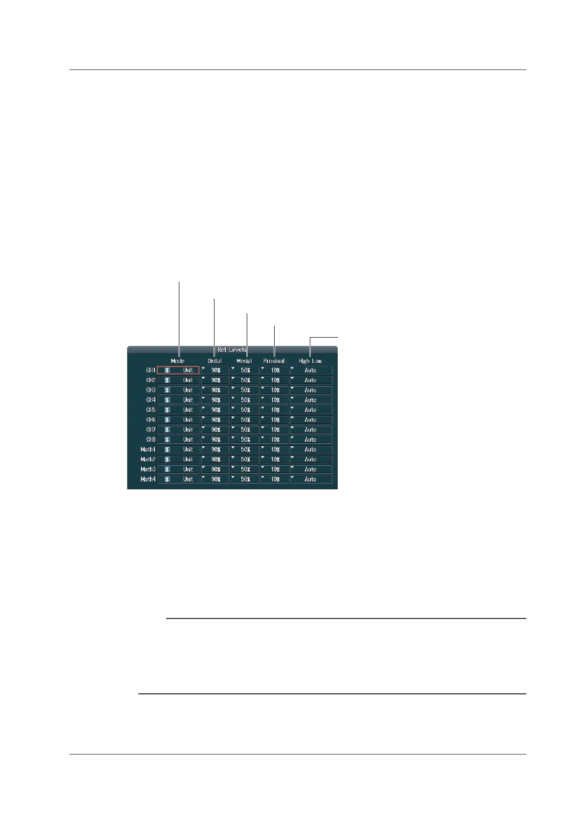
Setting the Reference Levels for Time Measurements (Ref Levels)
Press the Ref Levels soft key to display the following screen.
Set the mode for determining
high and low levels
(Auto, Max-Min, Histogram).
Set the proximal value (using the jog shuttle).
Set the mesial value (using the jog shuttle).
Set the distal value (using the jog shuttle).
Set the unit for the distal, mesial, and proximal
reference levels (% or Unit).
Setting the Measurement Source Window (Time Range)
Main: Set the measurement source window to the Main window.
Zoom1: Set the measurement source window to the Zoom1 window.
Zoom2: Set the measurement source window to the Zoom2 window.
Setting the Measurement Time Period (T Range1/T Range2)
Set the measurement time period within the window specified by Time Range.
Note
About the roll-mode display
• If the record length is 1.25 Mpoints or longer, measured time values such as Freq appear after you stop
waveform acquisition using the RUN/STOP key.
• If the record length is set such that waveform acquisition operates in Single mode (6.25 Mpoints or longer
for models without a memory option), automatically measured values of waveform parameters appear
when the roll mode display stops.

 Loading...


