1-2
IM DLM4038-02EN
Setting the Input Coupling (Coupling)
AC: Displays the waveform produced from only the AC component of the input signal through
1MΩ.
DC: Displays the waveform produced from both the DC and AC components of the input signal
through1MΩ.
DC50: Displays the waveform produced from both the DC and AC components of the input signal
through50MΩ.
GND: Displays the ground level.
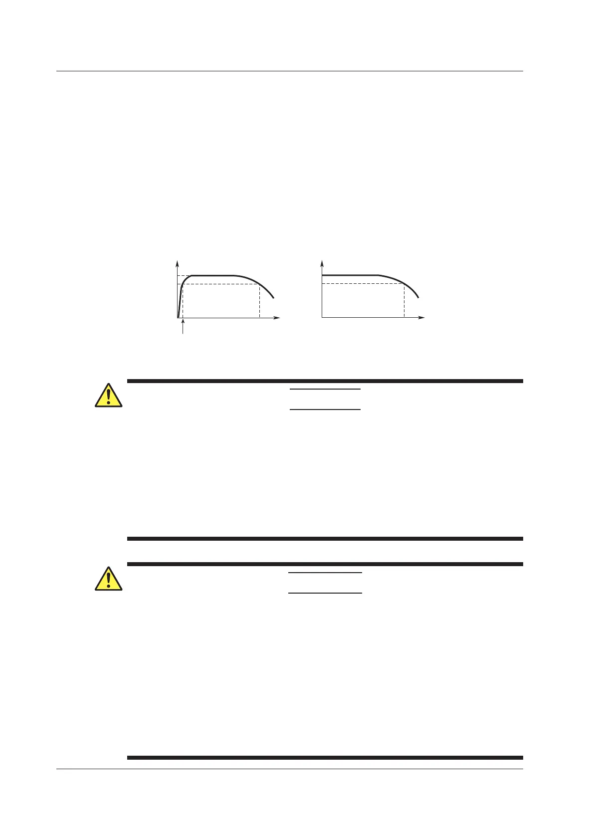
Input Coupling Settings and Frequency Response
The frequency responses when the DLM4000 is set to AC, DC, or DC50 are shown below.
Please note that when set to AC, the DLM4000 does not acquire low frequency signals or low
frequency components, as seen in the following figure.
0 dB
–3 dB
500 MHz
*
Attenuation
0 dB
–3 dB
500 MHz
*
With a 1:1 probe and a frequency less than or equal to 10 Hz
With a 10:1 probe and a frequency less than or equal to 1 Hz
Input frequency Input frequency
AC 1 MΩ DC 50 Ω or DC 1 MΩ
* The high-frequency –3 dB point differs according to the model and the voltage scale settings.
CAUTION
• Themaximuminputvoltagefor1MΩinputis150Vrmswhenthefrequencyislessthanor
equal to 1 kHz. Applying a greater voltage may damage the input section. For frequencies
above 1 kHz, damage may occur even if the voltage is less than 150 Vrms.
• Themaximuminputvoltagefor50Ωinputis5Vrmsor10Vpeak.Applyingavoltage
greater than either of these limits may damage the input section.
• If the input coupling is AC, in accordance with the frequency response, the input signal
is attenuated more in lower frequencies. As a result, even when a high voltage signal
is actually applied, it may not be measured as a high voltage signal. Furthermore, the
over-range indicator may not be displayed on the screen. As necessary, switch the input
coupling to DC to check the input signal voltage.
French
ATTENTION
• Latensiond’entréemaximalepouruneentréede1MΩestde150Vrmslorsquela
fréquence est inférieure ou égale à 1 kHz. L’application d’une tension supérieure pourrait
endommager la section d’entrée. Si la fréquence est supérieure à 1 kHz, une tension
inférieure à 150 Vrms pourra tout de même endommager la section d’entrée.
• Latensiond’entréemaximalepouruneentréede50Ωestde5Vrmsou10Vcrête.
L’application d’une tension supérieure à l’une de ces limites pourrait endommager la
section d’entrée.
• Si le courant du couplage d’entrée est alternatif (CA), conforme à la réponse en fréquence,
le signal d’entrée est davantage atténué aux fréquences plus basses. Par conséquent,
même si vous appliqué un signal de tension élevée, ce dernier risque de ne pas être
mesuré comme tel. De plus, le voyant de dépassement de plage risque de ne pas s’afficher
à l’écran. Le cas échéant, basculez le couplage d’entrée sur CC (courant continu) afin de
vérifier la tension du signal d’entrée.
1.1 Setting the Vertical Axis for Analog Signals
 Loading...


