12-26
IM DLM4038-02EN
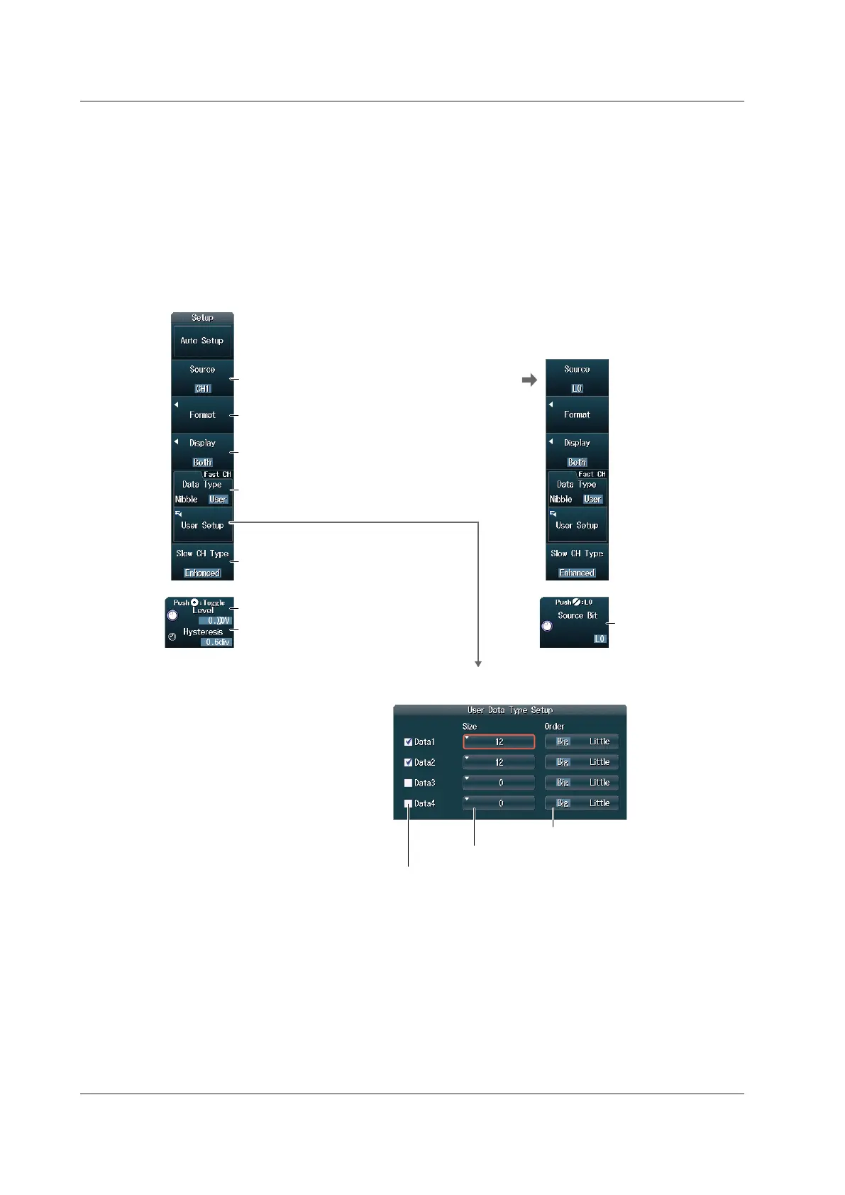
Manual Setup
After running auto setup, you can change the following settings and display decoded results.
• Source
• Format
• Display channel
• Fast channel data type
• Fast channel user data type
• Slow channel message type
• Level used to detect source states
• Hysteresis
Set the display channel
(Both, Fast CH, Slow CH).
Set the format. ► section 2.13
Set the user data type.
When the fast channel data type is User
Set the fast channel data type (Nibble, User).
Set the slow channel message type
(Short, Enhanced)
(only when the version is JAN2010).
► section 2.13
Set the source bit
(L0 to L7, A0 to A7,
B0 to B7).
1
Set the source (CH1 to CH8/LOGIC(L), LOGIC(A|B)).
1
When the Source Is LOGIC(L)
or LOGIC(A|B)
You can select CH8 or LOGIC(L), depending on which channel’s corresponding key (CH8 or L) is
illuminated.
LOGIC(A|B), A0 to A7, and B0 to B7 are available on models with the /L16 option.
2 The total number of bits for Data1 to Data4 is up to 24. If you try to exceed the total number of bits, the data
size of other pieces of Data is reduced.
Set the data size (0 to 24).
2
Select the check boxes for the items that you want to use
as comparison conditions.
Set the nibble byte order (Big, Little).
Set the level used to detect source states.
Set the hysteresis.
Setting the Format (Format)
This is the same as setting the format for the trigger type. For details, see section 2.13.
12.6 Analyzing and Searching SENT Signals (Option)

 Loading...


