12-53
IM DLM4038-02EN
Manual Setup
After running auto setup, you can change the following settings and display decoded results.
• Wiring system
• Clock source
• Data1 and 2 sources
• Chip select source
• Level used to detect source states
• Hysteresis
• Polarity
Press the Clock, Data1, Data2, or CS(SS) soft key to open one of the menus shown below.
The menu that appears varies depending on the source that is specified in the pressed soft key’s
menu.
The range within which the Data1, Data2, and chip select sources can be set changes depending on
the clock source as indicated below.
When the Clock Source Setting Is
CH1 to CH4, Math1, or Math2 CH5 to CH8/LOGIC(L),
*
Math3, or Math4 LOGIC(A|B)
*
Data1 and Data2 CH1 to CH4, Math1, or Math2 CH5 to CH8/LOGIC(L),
*
Math3, or Math4 LOGIC(A|B)
*
Chip select
CH1 to CH4, Math1, Math2,
or X (no source)
CH5 to CH8/LOGIC(L),
*
Math3, Math4,
or X (no source)
LOGIC(A|B)
*
* You can select CH8 or LOGIC(L), depending on which channel’s corresponding key (CH8 or L) is illuminated.
LOGIC(A|B) is available on models with the /L16 option.
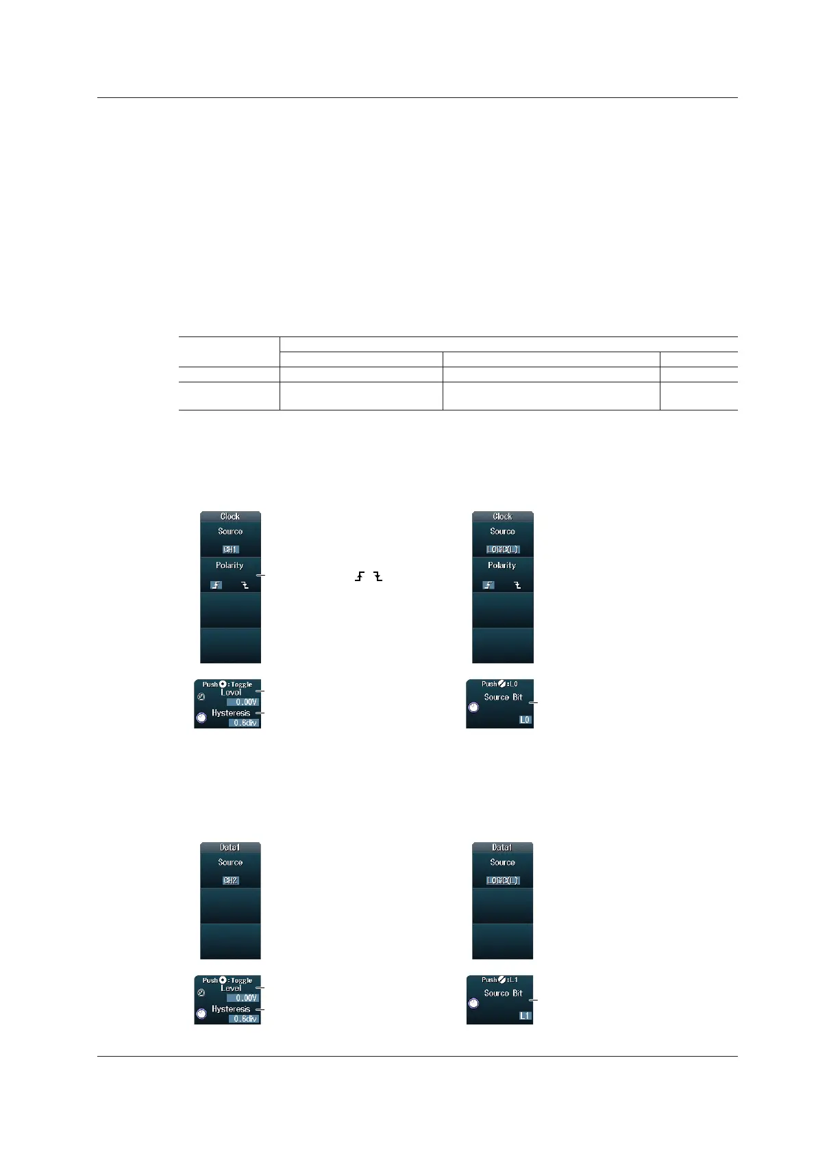
Setting the Clock Source (Clock)
When the Source is CH1 to CH8 or
Math1 to Math4
When the Source Is LOGIC(L) or
LOGIC(A|B)
Set the source bit (L0 to L7,
A0 to A7, B0 to B7).*
Set the polarity ( , ).
Set the level used to detect
source states.
Set the hysteresis.
Setting the Data1 and Data2 Sources (Data1 and Data2)
This section explains how to set the Data1 source. The Data2 source can be set in the same way.
Set the Data2 source when the wiring system is 4 Wire.
When the Source is CH1 to CH8 or
Math1 to Math4
When the Source Is LOGIC(L) or
LOGIC(A|B)
Set the source bit (L0 to L7,
A0 to A7, B0 to B7).*
Set the level used to detect
source states.
Set the hysteresis.
* A0 to A7 and B0 to B7 are available on models with the /L16 options.
12.10 Analyzing and Searching SPI Bus Signals (Option)

 Loading...


