12-59
IM DLM4038-02EN
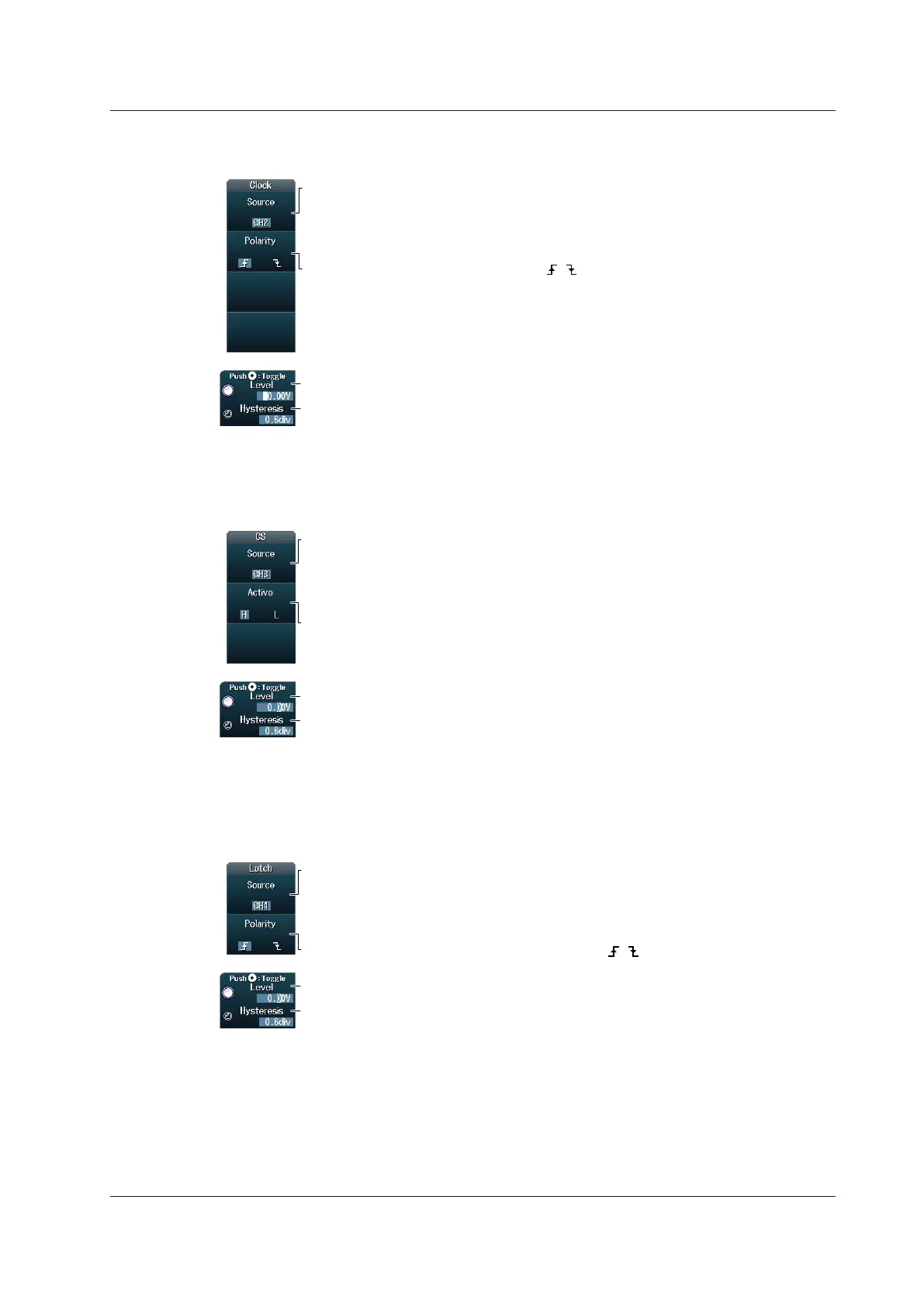
Setting the Clock Source (Clock)
Press the Clock soft key to display the following menu.
Set the timing for data source sampling ( , ).
Set the level used to detect clock source states.
Set the hysteresis.
Set the clock source.
• When the data source is a channel from CH1 to CH4,
set the source to CH1 to CH4.
• When the data source is a channel from CH5 to CH8,
set the source to CH5 to CH8.
Specify which clock source edge causes the data source to be sampled.
Setting the Chip Select Source (CS)
Press the CS soft key to display the following menu.
Set the level used to detect chip select source states.
Set the hysteresis.
Set the chip select source state to be recognized as the data source (L, H).
Set the chip select source.
• When the data source is a channel from CH1 to CH4,
set the source to CH1 to CH4 or X.
• When the data source is a channel from CH5 to CH8,
set the source to CH5 to CH8 or X.
When the data source is sampled in sync with the clock source, use the chip select source to
control the period for which the DLM4000 tests the data source.
Setting the Latch Source (Latch)
Press the Latch soft key to display the following menu.
Set the timing for data source pattern comparison ( , ).
Set the level used to detect latch source states.
Set the hysteresis.
Set the latch source.
• When the data source is a channel from CH1 to CH4,
set the source to CH1 to CH4 or X.
• When the data source is a channel from CH5 to CH8,
set the source to CH5 to CH8 or X.
Specify the timing at which the data source pattern sampled in sync with the clock source is
compared with the specified pattern.
12.11 Analyzing and Searching User-Defined Serial Bus Signals
 Loading...


