2-15
IM DLM4038-02EN
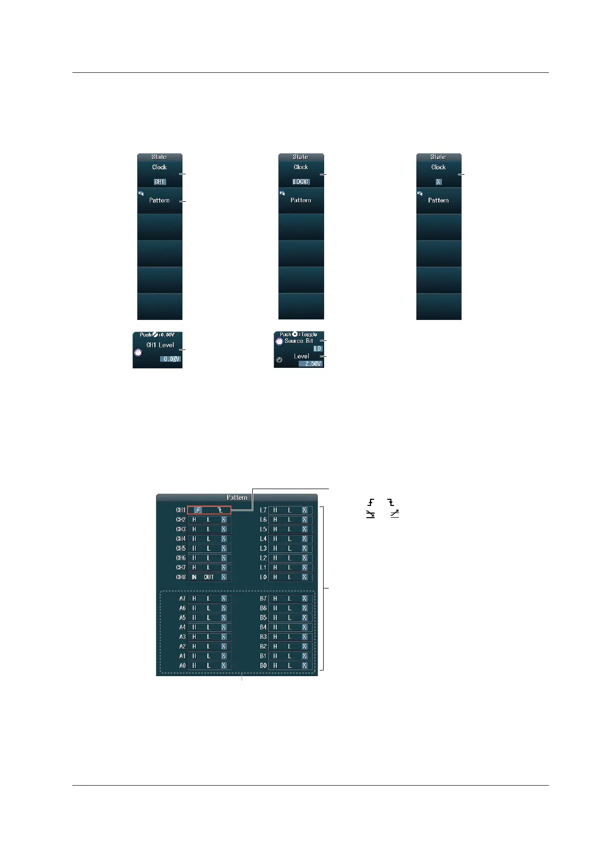
Setting the State Conditions (State)
Press the State soft key to display one of the menus shown below. The menu that is displayed varies
depending on the specified clock source.
When the Clock Source Is a
Channel from CH1 to CH8
When the Clock Source
Is LOGIC
Is Not Specified
Set the clock source
(CH1 to CH8).
Set the clock source
(LOGIC).
Set the clock
source pattern.
Set the clock source
(X).
Set the level used to
detect the slope and
pattern of each signal.
Set the source bit (L0 to L7, A0 to A7, B0 to B7).*
Set the level used to detect the slope
and pattern of each signal.
* A0 to A7 and B0 to B7 are available on models with the /L16 options.
Setting the Clock Source Pattern
Press the Pattern soft key to display a menu. The menu that is displayed varies depending on the
specified clock source.
• When the Clock Source Is a Channel from CH1 to CH8 or LOGIC
Example: When the Clock Source Is CH1
Set the slope for the clock source signal.
• Select or when the window comparator is off.
• Select or when the window comparator is on.
Set the patterns for signals other than the clock source.
• Select H, L, or X when the window comparator is off.
• Select IN, OUT, or X when the window comparator is
on.
/L16 option
• When the Clock Source Is Not Specified
The same menu appears as that shown above for when the clock source is a channel from CH1
to CH8 or LOGIC. Because no clock source is specified, you can specify all of the signal states
for CH1 to CH8 and LOGIC as state conditions.
2.8 Triggering on State Width
 Loading...


