2.
On a module with logic inputs or sub
channels, expand the menu, and set
each bit or sub channel.
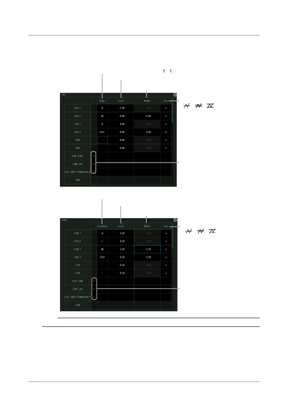
Set the trigger level.
Set the hysteresis.
( , , )
Set the edge detection condition ( , , IN, OUT, –).
Set the level width
(when the edge detection condition is set to IN or OUT).
Set the achievement condition (H, L, IN, OUT, —).
OR trigger
On a module with logic inputs or sub
channels, expand the menu, and set
each bit or sub channel.
Set the trigger level.
Set the level width
(when the edge detection condition is set to IN or OUT).
AND Trigger
Set the hysteresis.
( , , )
If linear scaling is applied to the trigger source, set the trigger level using a linearly scaled value.

 Loading...


