Chapter 2
Channel Setup
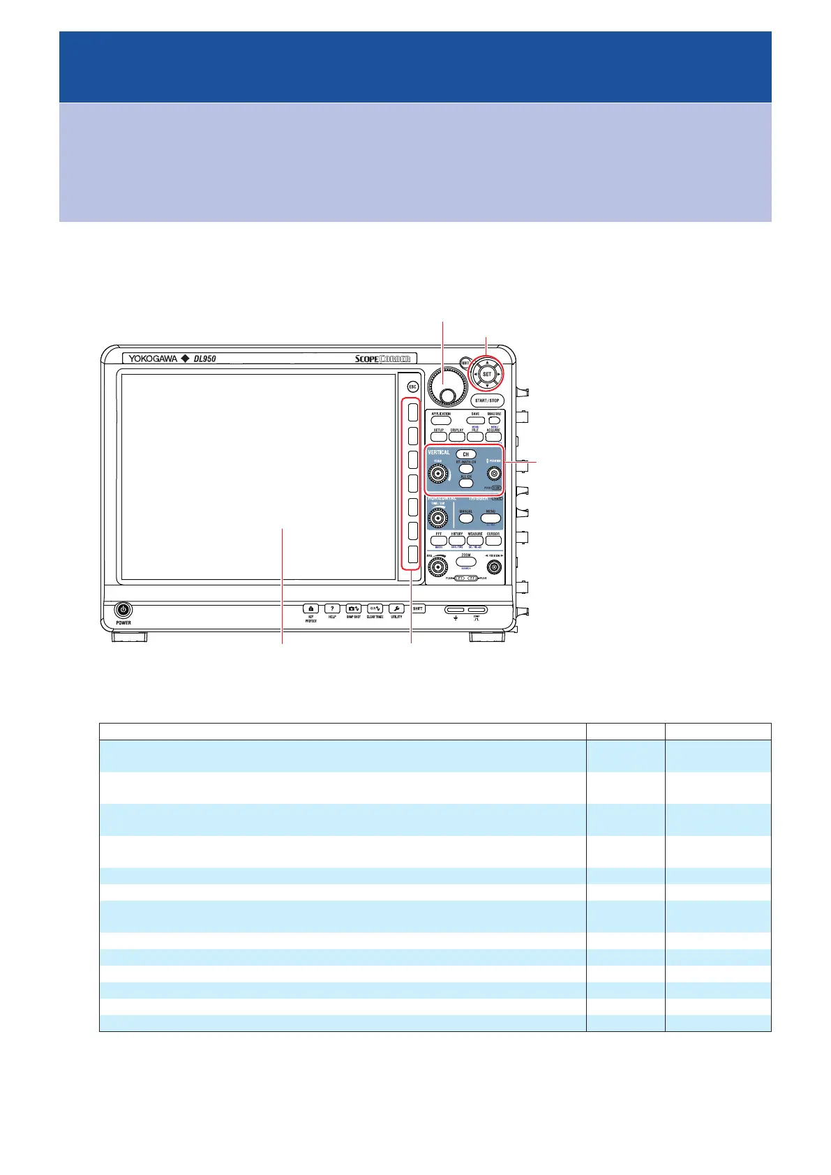
Main Control Areas Used in This Chapter
You can also use the touch panel.
Jog dial
Panel keys used in this
chapter (excluding RT
MATH CH)
Arrow keys
Soft keys
Touch panel
Operation Modes Applicable to the Sections in This Chapter
ü
: Applicable, -: Not applicable
Section Scope Mode Recorder Mode
2.1 Configuring Voltage Measurements (on modules other than 16-CH temperature/
voltage input modules)
ü ü
2.2 Configuring Voltage Measurements (on 16-CH temperature/voltage input
modules)
ü ü
2.3 Configuring Temperature Measurements (on modules other than 16-CH
temperature/voltage input modules)
ü ü
2.4 Configuring Temperature Measurements (For 16-CH temperature/voltage input
modules)
ü ü
2.5 Configuring Strain Measurements
ü ü
2.6 Configuring Acceleration Measurements
ü ü
2.7 Configuring Frequency, Revolution, Period, Duty Cycle, Power Supply
Frequency, Pulse Width, Pulse Integration, and Velocity Measurements
ü ü
2.8 Configuring Logic Signal Measurements
ü ü
2.9 Configuring the Monitoring of CAN and CAN FD Bus Signals (/VCE option)
ü ü
2.10 Configuring the Monitoring of LIN Bus Signals (/VCE option)
ü ü
2.11 Configuring the Monitoring of SENT Signals (/VCE option)
ü ü
2.12 Displaying the All Channel Setup Menu
ü ü
2.13 Setting the Digital Filter (/G03, /G05 option)
ü ü
* The settings may vary depending on the operation mode.

 Loading...


