Theory 7
Agilent Nano Indenter G200 User’s Guide 7-3
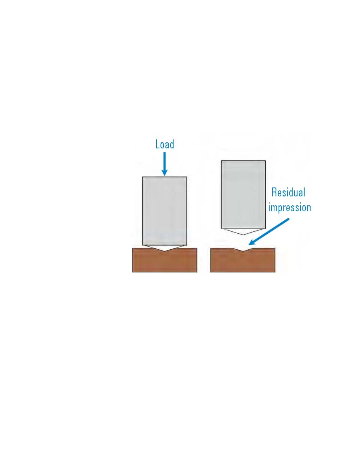
Indentation Process Overview
As the indenter is driven into the material, both elastic and plastic
deformation cause the formation of a hardness impression conforming
to the shape of the indenter to some contact depth, h
c
, as shown in
Figure 7-1. As the indenter is withdrawn, only the elastic portion of the
displacement is recovered; this recovery enables one to determine the
elastic properties of a material.
Figure 7-1Schematic of indentation load (left) and residual impression
(right)
Continuous Load-Displacement Data
A set of continuous load-displacement data is shown in Figure 7-2 on
page 7-4. Some important quantities are:
• Peak load (P
max
)
• Displacement (h
max
)
• Residual depth after unloading (h
f
)
• Slope (S) of the initial portion of the unloading curve, where
S= dP/dh (4)

 Loading...