Commonly Used Procedures 6
Agilent Nano Indenter G200 User’s Guide 6-77
Adjusting the Vibration Isolation Table
The vibration isolation table should be adjusted so that it rests in the
middle of its vertical range. Therefore, before adjusting the isolation
table, install the sample tray with the samples being tested into the
machine.
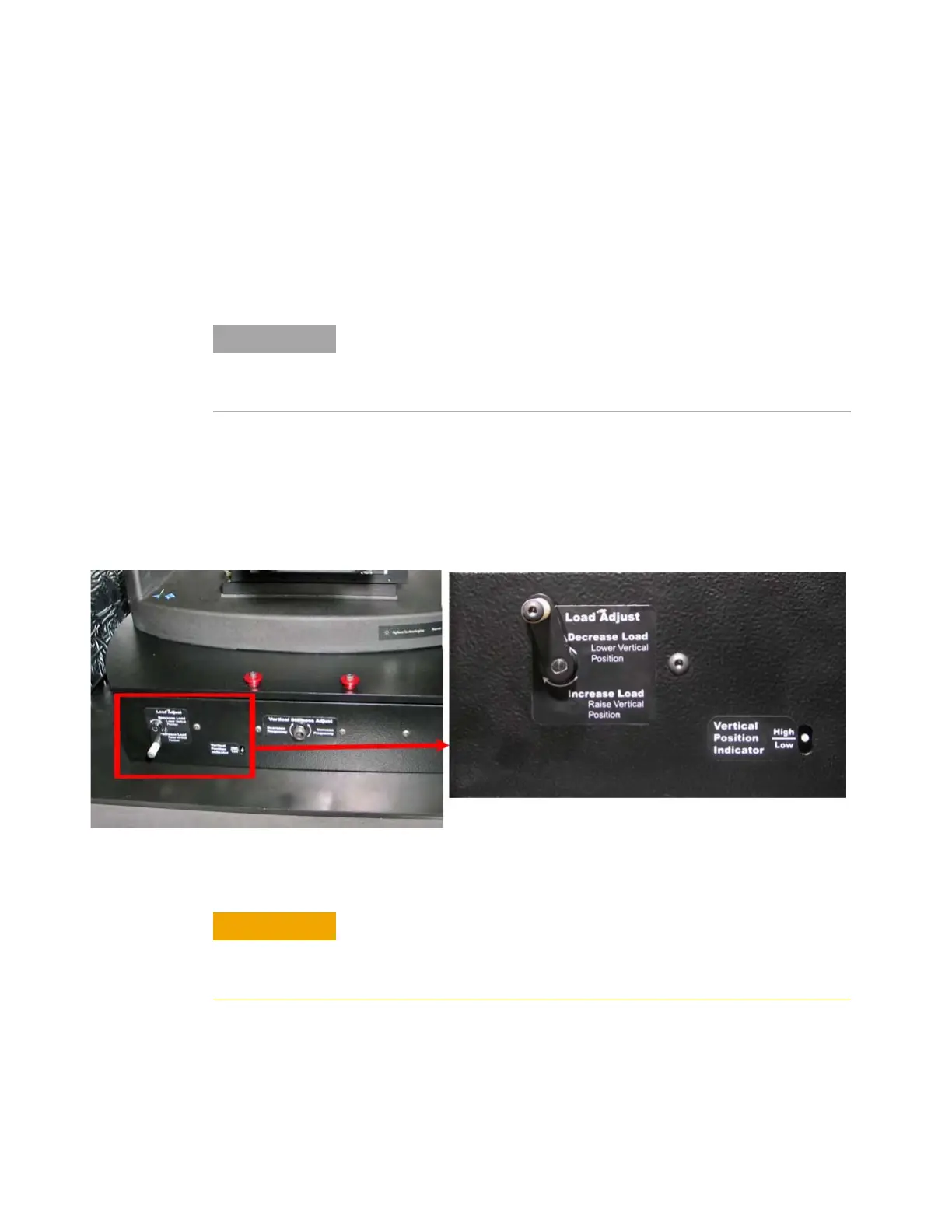
1 Locate the Vertical Position indicator and the Load Adjustment
crank, as shown in
Figure 6-104.
You should be able to turn the crank with only a few inch-pounds of
torque.
Figure 6-104Adjustment locations on vibration isolation table
The Vertical Position indicator consists of a pin that moves in a vertical
slot in the front cover and a sticker with a horizontal line that shows the
optimal vertical position corresponding to the maximum vertical travel.
Cables, hoses, and other items connected to the machine can affect
adjustments to the vertical position of the table. Make sure that such
items are positioned such that the table isolator can oscillate freely in the
vertical direction.
To avoid damage to the table, turn the Load Adjustment crank only
clockwise when the pin is below the line and only counter-clockwise
when the pin is above the line. Never force the Load Adjustment crank,
which could cause damage.

 Loading...