Commonly Used Procedures 6
Agilent Nano Indenter G200 User’s Guide 6-36
Figure 6-50Tip Area and Frame Stiffness Calibration dialog box
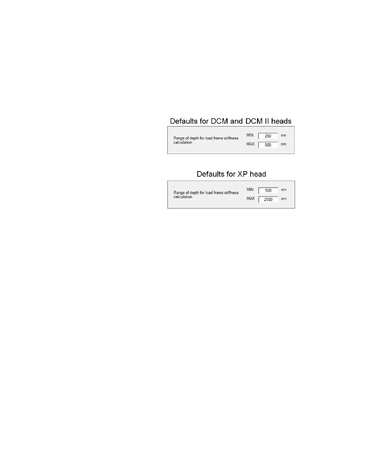
For the Range of depth for load frame stiffness calculation parameters,
use the range values as shown in
Figure 6-51 on page 6-36.
Figure 6-51Default values for Range of depth for load frame stiffness
calculation for different indenter heads
Area Function Information
For the area function information, there are two choices.
• Option 1 assumes the modulus of the test material is known.
• Option 2 assumes the ideal area function defines the tip well at
large displacements.
Regardless of the option chosen, the Range of depth for area calculation
default range is set for the indenter head as noted in
Figure 6-52 and is
almost always appropriate.

 Loading...