Scratch Testing E
Agilent Nano Indenter G200 User’s Guide E-8
Markers
All of these markers discussed in this section are movable. For more
information on moving markers, see
"Setting the Surface Marker" on
page 272 in Chapter 6, "Commonly Used Procedures".
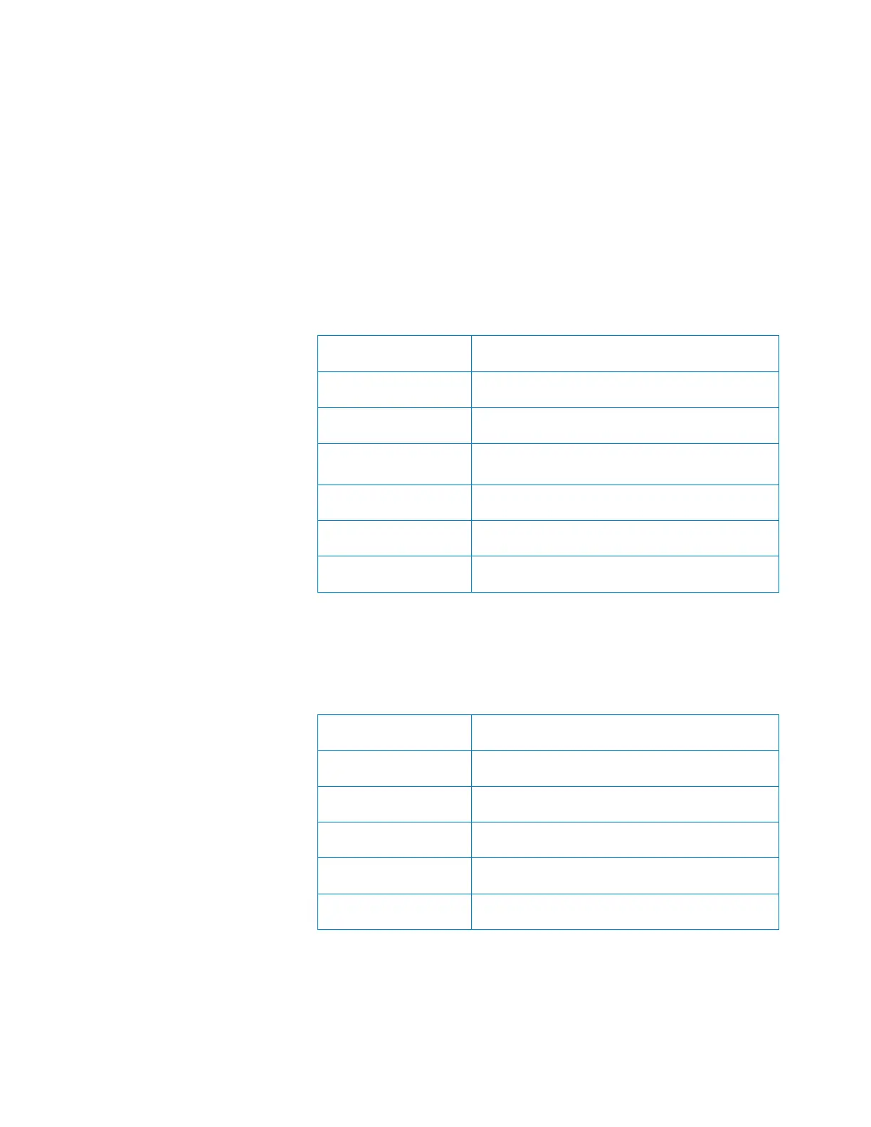
When viewing Penetration Curves With Roughness (nm) data, there are
six markers, outlined in
Table 1.
Table 1 Six Markers for Penetration Curves
When viewing Cross Profile Topography (nm) data, there are five
markers, outlined in
Table 2.
Table 2 Five Markers for Cross Profile Topography
Marker Character Marker Function
a Beginning of the scratch
b End of the pre-scratch profile
C Critical point (start of fracture; appears only
when a fracture occurs)
d End of Scratch
e End of post-scratch profile
M Beginning of the final profile
Marker Character Marker Function
0 Beginning of the cross profile
1 End of the cross profile
O Top left pile up
P Top right pile up
G Bottom of the groove

 Loading...