Dynamic Contact Module II B
Agilent Nano Indenter G200 User’s Guide B-5
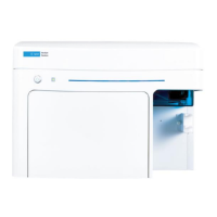
Figure B-7Insert locking pins at 90 degrees
8 Place two locking pins through the collar (bottom cover) and
indenter shaft by gently inserting them through the collar and shaft
with a twisting motion, using minimal force. If the first locking-pin
hole is difficult to penetrate, try the other hole first.
9 Click OK in the Caution! dialog box.
10 Exit and restart NanoSuite.
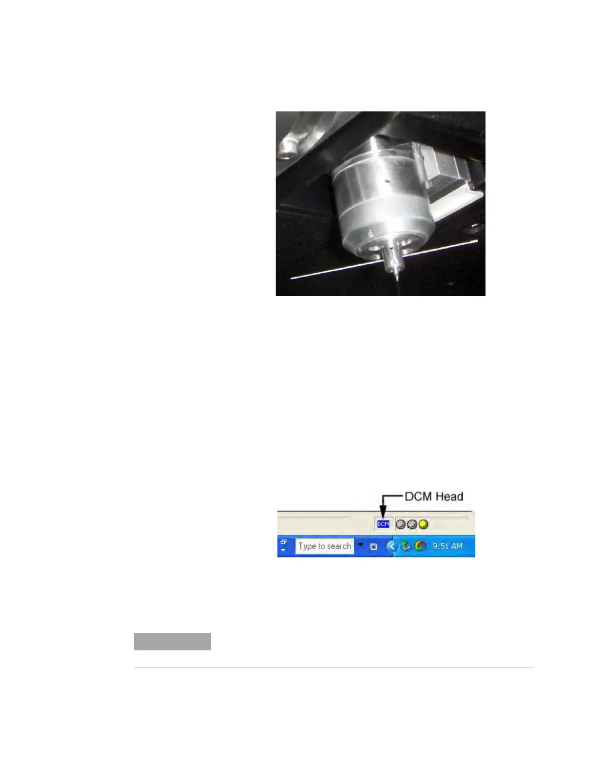
11 Find the head-indicator icon on the Status Bar in NanoSuite.
12 Confirm the head-indicator icon is set to DCM highlighted in blue as
shown in
Figure B-8.
Figure B-8DCM II icon on Status Bar
Using the DCM II head is identical to using the XP head, except that the
data from the DCM
II head has better resolution.

 Loading...